44 en | Connections MAP 5000
2019-09 | 25 | F.01U.168.332 Installation manual Bosch Security Systems B.V.
Bus wiring without consideration of the power supply
3.1.3 Splitting the external data bus with a CAN splitter module
The external BDB can be splitted into two independent and isolated stubs to connect
keypads, gateways and further power supplies. This way, flexible wiring into different
directions with up to 500 m cable length as well as a higher reliability can be achieved.
For information on installing a CAN splitter module, refer to the correspondent installation
manual and datasheet.
CAN splitter module wiring without consideration of the power supply
ICP-MAP0012
Max. 500 m
Max. 500 m
See also
– Planning the system with ICP-MAP0012 CAN splitter module, page 11
3.2 Connecting the control center
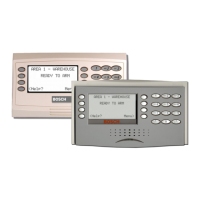
The BDB supports up to 32 control centers. The power supply of remote control centers can
be ensured with the expansion enclosure (power supply application).
VdS programming instruction
4 Only assign one area (where applicable with overlapping dependent partition areas) to a
control center.
Exception:
Mutually independent areas may be assigned to the control center of the control panel area.
 Loading...


