MAP 5000 Connections | en 55
Bosch Security Systems B.V. Installation manual 2019-09 | 25 | F.01U.168.332
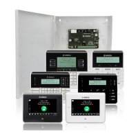
3.9 Installing the control center
Mounting location
Mount the control center onto the wall so that the user interface is at a comfortable level for
the end user. Typical installations of the touchscreen are at shoulder level, which is
approximately 150 to 160 cm (59 to 62 in) above the floor. It must be guaranteed by
corresponding positioning of the control center or by organizational measures that only the
user has an optimum view of the touchscreen.
Mounting the control center
1. Unlock the control center base and remove the cover.
2. Use the control center base to mark the holes on the mounting surface.
3. Refer to Data bus connection of the control center on the external BDB, page 45 for wiring
instructions.
4. Replace the control center cover on the base.
The cover automatically locks to the base.
5. Secure the cover using the two screws M3 x 20 mm (F.01U.172.636).
6. The fed-in cable must be provided with strain relief.
7. The adhesive seal must be attached after completion of all work.
Opening the control center
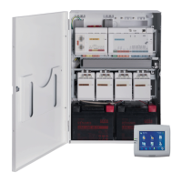
3.10 Final power connections
1. Connect AC wires to the AC terminal block.
2. Connect the battery wire leads to the batteries.
Do not connect the batteries to the power supply at this time.
3. Switch the AC breaker on.
4. Ensure that there are no power-related trouble conditions.
Warning!
Ensure that the AC LED indicator on the power supply turns on steady before you connect the
battery terminal to the power supply.