MAP 5000 Connections | en 47
Bosch Security Systems B.V. Installation manual 2019-09 | 25 | F.01U.168.332
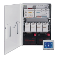
1 Battery circuit 2
2 Battery circuit 1
3 Connection for thermistor
4 Power connection to main panel
5 Input for tamper switch, is activated by configuration for remote operation of
the power supply on the external BDB.
6 Output for voltage supply (switched), supervised, nominal voltage 24 V DC
7 Data bus - connection A
8 Data bus - connection B
9 Output for AC fail and summary power supply trouble (optional)
10 AC connection
3.5 Connecting the LSN gateway
Notice!
When connecting an LSN component, ensure that you follow local standards and guidelines
when planning the system installation.
The following applies for VdS systems: Each area must be supplied with power
independently. The outputs AUX1 and AUX2 on the LSN gateway (for max. two areas) or the
voltage outputs of the fuse plate (SIV) (for additional areas) are available for this purpose.
Shielded stub and loop wiring
For both stub and loop wiring, the following additional requirements apply for shielded wires:
– Usage of an additional shielding wire from the central unit
– Routing across the shortest possible distance to the earth terminal
– Looping the shield wire through the LSN elements
Other connections of the additional shielding wire at other locations are not permitted. With
loop wiring, the additional shielding wire must be connected at both loop ends.