1 689 989 355 2019-04-08| Bosch Automotive Service Solutions GmbH
12 | MTS 6534 / MTS 6535 | Getting Startedenen
9. Specify the network name:
$ If your access point uses a hidden SSID or if you
are not within range of the access point you will
select the Enter Network Name [SSID]: radio but-
ton and type the network name.
$ If you are within range of your wireless access
point, choose the Select from available network
list radio button and then select Refresh to cause
the VCI to search for wireless network signals. The
detected networks are displayed in the Network
Name box.
10. After you have entered the network name, select
Configure.
11. Enter the security settings that are required by your
network, then select Next.
12. Select Yes to reconfigure your VCI, or if you want to
start over select No.
13. Choose the Properties tab to verify that the VCI is
configured correctly. You can also disconnect the
USB cable to verify that the wireless connection is
working.
14. Record or print your settings as they are displayed on
the Properties tab for future reference.
7.3.2 Enabling Point-to-Point Wireless Communica-
tion
Your VCI can be configured for Point-to-Point Wireless Com-
munication. Before starting, please verify the following:
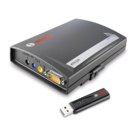
i Your VCI kit is on of the Wireless-Point-to-Point kits
(for part numbers, see "10.3 Spare and wearing
Parts") which includes the VCI assembly with two
Wireless 802.11n USB Adapters.
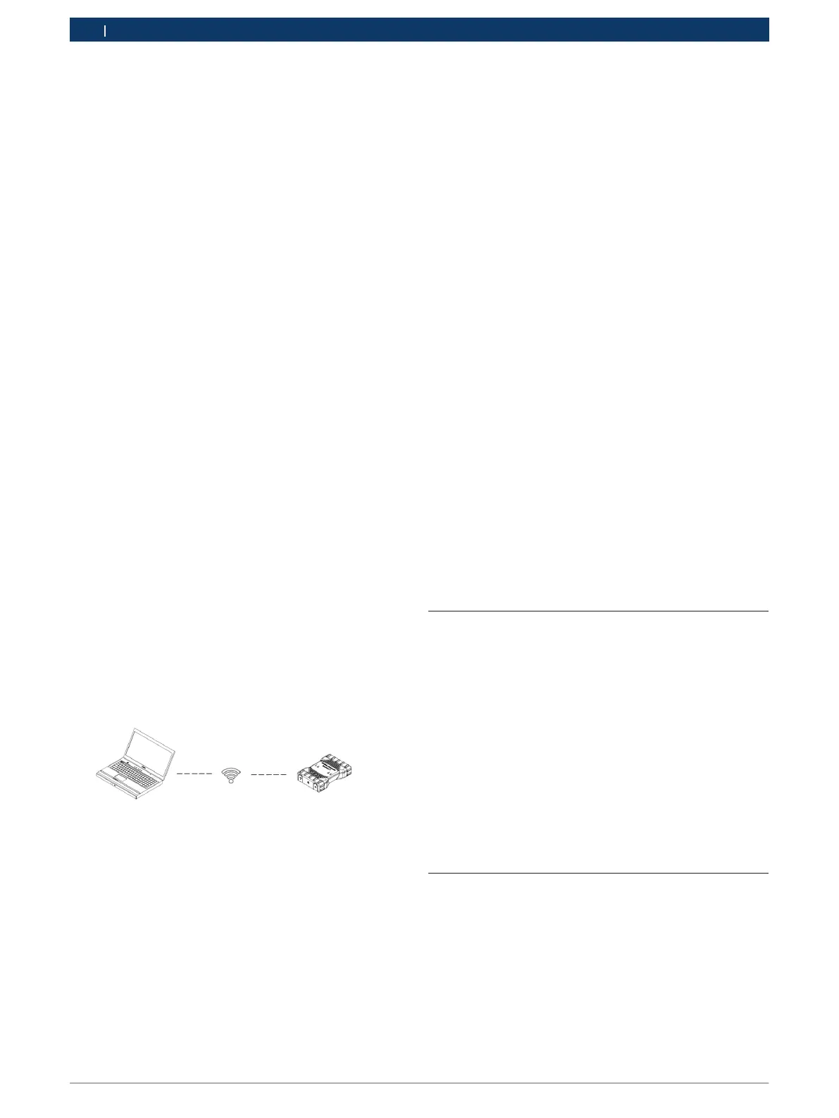
The following illustration shows a single VCI connected
to a laptop PC using Point-to-Point Wireless communica-
tion.
If you need to re-configure Point-to-Point on your VCI,
use the following procedure. Note that the steps present-
ed below may slightly differ depending on your version
of the Windows operating system.
1. Insert the Wireless USB adapter in an available USB
port on your PC. Do not plug the wireless adapter
into a USB hub.
2. Power-on your PC.
3. Connect the VCI to your PC using the USB cable and
allow the VCI to boot completely. Do not plug the VCI
USB cable into a USB hub.
4. Start the VCI Manager software by double-clicking the
icon on the PC desktop.
5. The Point-to-Point connection is automatically config-
ured. Wireless communication will be available when
you are powered through the DLC Cable.
If you have the need to reset your Point-to-Point pass-
phrase, you can use the following steps. Note that the
steps presented below may slightly differ depending on
your version of the Windows operating system.
1. Right click the Wireless Networks Icon on the right
hand side of the taskbar.
2. Select Open Network and Sharing Center.
3. Select Manage Wireless Networks from the left col-
umn.
4. Select Change adapter menu and choose VCI from
the list.
5. Remove your stored Point-to-Point network. The
name will contain VCI and the last 8 digits of the VCI
serial number, (VCIxxxxxxx).
6. When you reconnect the VCI to the PC using the USB
cable, a new passphrase will be established.
7.3.3 Set Factory Default
Selecting the Set Factory Default button on the Network
Setup tab reconfigures your VCI to the Point-to-Point
communications settings it had when it left the factory.
Any software upgrades that have been installed to the
VCI are still installed. When the VCI reset is finished, the
VCI Manager software displays the VCI Explorer tab. All
wireless AP configurations will be lost.
7.4 Connecting the VCI to a Vehicle
The VCI Vehicle Communication Interface kit contains
an external test equipment (OBD) cable that connects
the VCI to the vehicle’s SAE J1962 Data Link Connector
(DLC).
Refer to the electrical wiring diagram for the vehicle you
are testing to determine the location of the DLC on the
vehicle.
1. Connect the 26-pin end of the OBD-cable to the top
of the VCI, then tighten the screws.
2. Connect the 16-pin end of the OBD-cable to the
vehicle DLC connector.
7.5 Powering the VCI
The VCI will be powered by the vehicle’s 12V/24V bat-
tery.
 Loading...