1 689 989 355 2019-04-08| Bosch Automotive Service Solutions GmbH
2 | MTS 6534 / MTS 6535 | enen
1. Symbols Used 3
1.1 Warning Notices - Structure and Meaning 3
1.2 Symbols in this Document 3
1.3 Symbols on the Product 3
2. Warranty information 3
2.1 Agreement 3
4. Safety Instructions 4
3. User Information 4
4.1 Electromagnetic Compatibility 5
4.2 Electronic Waste Disposal 5
4.3 FCC Compliance 5
4.4 Range of application 5
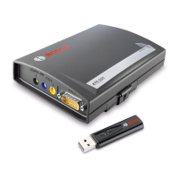
5. Product Description VCI 5
5.1 Intended use 5
5.2 User group 5
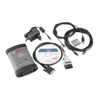
5.3 VCI Kit Contents 6
5.3.1 Non-Wireless kits 6
5.3.2 Wireless P2P kits 6
5.4 VCI Connectors and Controls 6
5.4.1 Front and back side 6
5.4.2 VCI without display 6
5.4.3 VCI with display 7
5.5 Universal Serial Bus (USB) 7
5.6 Wireless Local Area Network (WLAN) 7
5.7 VCI Manager Software 7
5.8 Additional VCI Features 7
5.8.1 Data Link Connector and Cable 7
5.8.2 Power Source 7
5.8.3 LED Indicators 7
5.9 LED status 8
5.9.1 LED Power 8
5.9.2 LED Error Indicator 8
5.9.3 LED Vehice Communication 8
5.9.4 LED PC Host Communication 8
6. Product description TS1 Trigger switch 8
6.1 Intended use 8
6.2 Prerequisites 8
6.3 Product description 8
6.4 Operation 9
6.5 Information on Data Protection 9
7. Getting Started 9
7.1 Installing the VCI Manager Software 9
7.2 Setting Up the VCI Hardware 9
7.2.1 Installing Your Wireless Adapter 9
7.2.2 Identifying Your VCI 10
7.2.3 Updating the VCI Software 10
7.2.4 Configuring the VCI using VCI Manager 10
7.2.5 Check PC and VCI Software Versions 11
7.3 Setting Up Wireless Communications 11
7.3.1 Enabling Access Point Wireless
Communication 11
7.3.2 Enabling Point-to-Point Wireless
Communication 12
7.3.3 Set Factory Default 12
7.4 Connecting the VCI to a Vehicle 12
7.5 Powering the VCI 12
8. Finishing Up 13
9. Troubleshooting 13
9.1 VCI Does Not Pass Power On Self-Test (POST) 13
9.2 VCI Error LED Lights After Power On 13
9.3 VCI Fails to Power Up 13
9.4 Vehicle LED is Blinking Red 13
9.5 Suspected Defective Data Link Connector (DLC)
Cable 13
9.6 Wireless Communication with Network
Unsuccessful using WLAN dongle 13
9.7 VCI Manager Displays the Yellow Icon over the
VCI after previous use 14
9.8 PC Application is Unable to Communicate with
the VCI over USB 14
9.9 PC Application is Unable to Communicate with
the VCI over Wireless 15
10. Cleaning and Maintenance 15
10.1 Cleaning and Storing 15
10.2 Recovering the VCI Software 15
10.3 Spare and wearing Parts 15
10.4 Recovery Procedure 16
11. Decommissioning 16
11.1 Temporary shutdown 16
11.2 Change of location 16
11.3 Disposal and scrapping 16
12. Glossary 17
13. Hardware Specifications 17