1 689 989 355 2019-04-08| Bosch Automotive Service Solutions GmbH
8 | MTS 6534 / MTS 6535 | Product description TS1 Trigger switchenen
5.9 LED status
5.9.1 LED Power
Color Status Function
Off
- VCI is not powered or overvoltaged. If over-
voltaged, Error LED indicator lights up.
Green
Lights up VCI is correctly powered via PC or vehicle.
5.9.2 LED Error Indicator
Color Status Function
Off
Off No error
Red
Lights up R Check completed and firmware failed
to load, system failed to start properly,
firmware mismatch.
R Check is not OK.
R Recovery active.
R Overvoltage on at J1962 connector.
5.9.3 LED Vehice Communication
Symbol Color Function
Off
- No active vehicle communication.
Green
initial-
ly Lights
up
VCI is powered by vehicle and has estab-
lished communication with vehicle.
Flash Active Vehicle communication (DIAG
mode).
Amber Flash active reprogramming
(RP mode by VCI script engine).
White Flash active Vehicle data recording
(VDR mode by VCI script engine).
Red Flash VCI is not able to perform vehicle commu-
nication.
5.9.4 LED PC Host Communication
Symbol Color Function
Off
- no active host communication.
Green
Flash VCI is connected to the PC via PDU or
J2534 or VCI Manager Application.
Lights up successful connection to workshop access
point (infrastructure mode) in use case
"mobile device".
Red Flash Failed connection to workshop access
point (infrastructure mode) in use case
"mobile device".
6. Product description
TS1 Trigger switch
6.1 Intended use
The TS1 Trigger switch and MTS 6534/6535 permit the
read-out and display of emission-related diagnostic data
via the OBD interface of gasoline and diesel passenger
vehicles. This diagnostic data can help to establish the
cause of problems in the vehicle.
! Use of TS1 Trigger switch and MTS 6534/6535 and
recording of diagnostic data while driving may only
be performed by trained and instructed employees
of the service workshop.
6.2 Prerequisites
OBD interface (OBD-2 or EOBD) for the vehicle to be
tested and MTS 6534/6535.
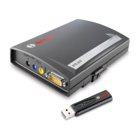
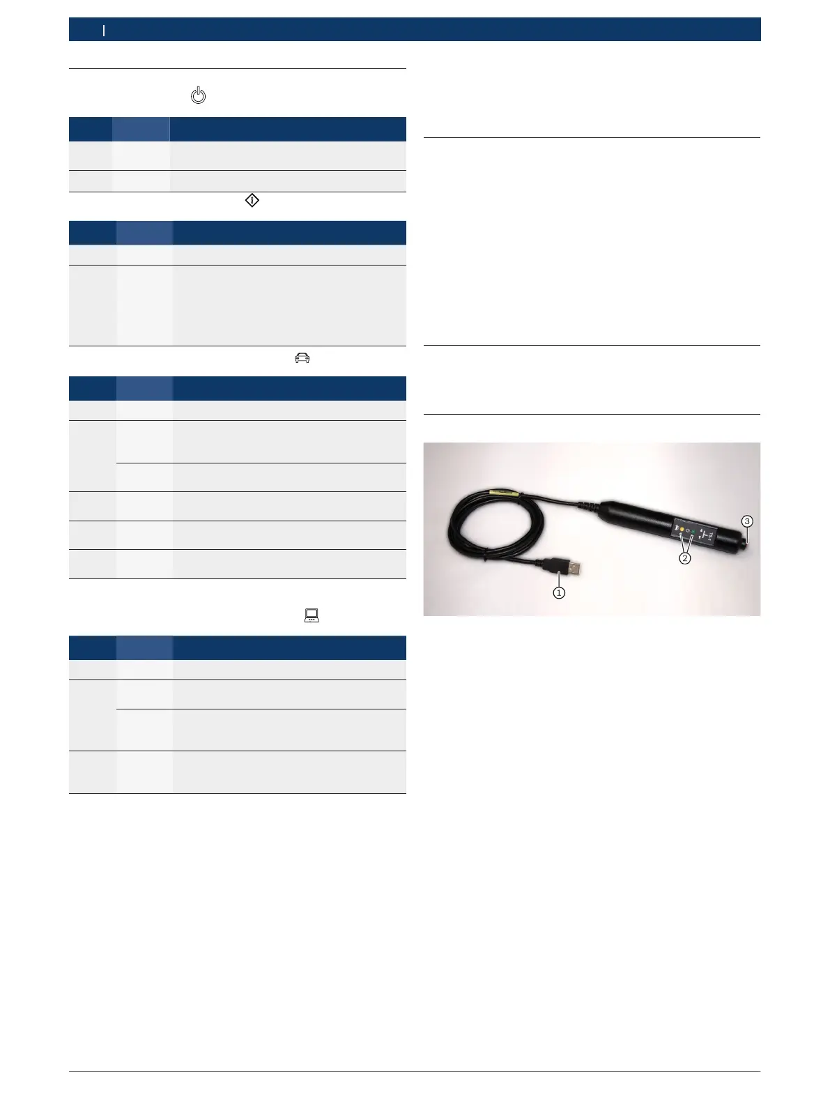
6.3 Product description
Fig. 1: TS1 Trigger switch
1 USB connection to MTS 6534/6535
2 LEDs for status lights, illumination of LED depends on the appli-
cation and the step used (see instructions for specific test step)
3 Recording button