PLENA power amplifiers Connection and indicators | en 9
Bosch Security Systems B.V. Installation and operation manual 2018.11 | V1.2 | LBB193x/x0
5 Connection and indicators
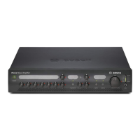
5.1 Front panel indicators
0 dB
-6 dB
-20 dB
taehrevOyrettaB MainsPilot-Tone
Status
1 2 3 4 5 6
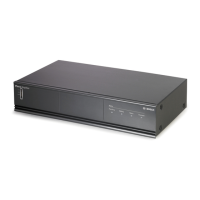
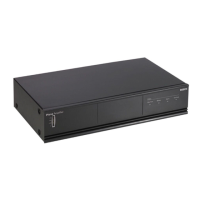
Figure5.1: LBB1930/20, LBB1935/20 and LBB1938/x0
1. VU meter LED’s for -20, -6, 0dB and power ON.
2. Pilot‑tone supervised function that monitors a 20kHz pilot tone.
3. Battery supervised function to indicate battery operation.
4. Mains supervised function to indicate mains supply.
5. Overheat supervised function to give warning of overheating.
6. Air inlet cooling is made by forced ventilation from front to back. Amplifiers can be
stacked on top of each other. A supply of cool air from the front is necessary.
5.2 Rear panel connectors and switches
Priority Only No Priority
100V 0 1 00V 0
Priority Controlled Output
O On
24V DC In
Apparatus delivered
connectored for 230V~
Main Power
BatteryInput
Fault Relays' Output
NO COM NC
O On
NO COM NC NO COM NC
Input 1Pri ority
Loopthrough1
Input 2Progr am
Loopthrough2
Input 1Pri ority
2...24V- Input1
0V- Input2
Input 2Enable
2..24V- Enable
0V- Mute
100V
0
Sla veI nput100V
+
+
-
-
100V
0
70V
0
8ohm
100V/70V
Sele ction(12A)
Priori tyOnly
0
0
No Priority
Priori ty
F701
F702
Battery
Power
Detection
Pilot-tone
Detector
230V~ 240V~
Rated input
Power : 1600VA
Input 1
Pr iority
Slave Input
100V
Input 2
Enable
100V 0
100V 70V0 0 8
Direct O utput
InputInput
Input 2-Progr amInput 1-Priority
2..24V
Defaul t O
GND 2. .24V
Defaul t On
GND
20 19 18 17 16 1415 13
1 2 3 5 64 7 8 9
12
11
10
Figure5.2: LBB1930/20 and LBB1935/20

 Loading...