Bosch Security Systems | 2005-04 | 9922 141 10364en
Plena Voice Alarm System | Basic System Manual | Installation en | 21
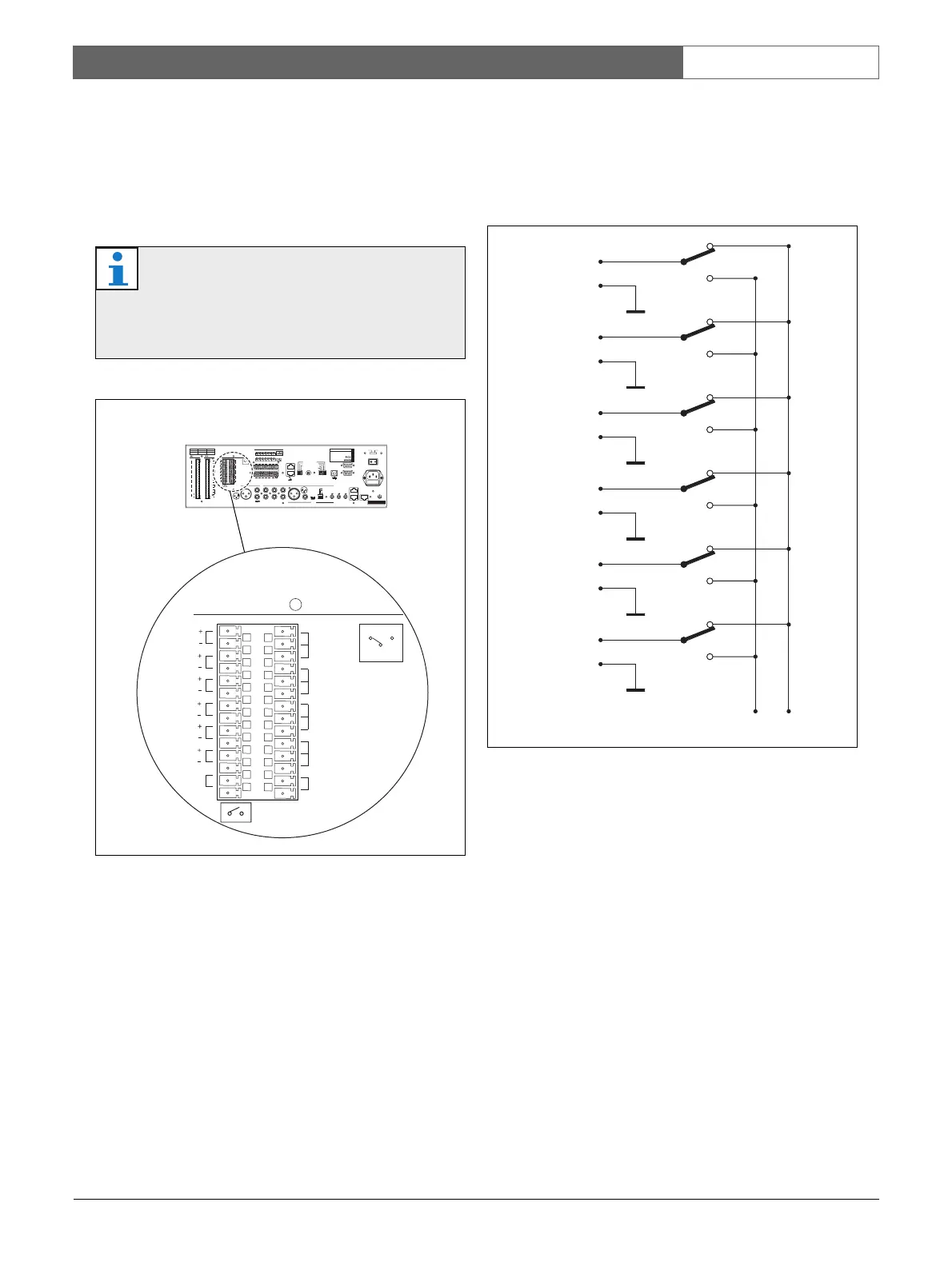
3.11 Volume overrides
The voice alarm controller has 6 override outputs; 1 for
each zone in the system (see figure 3.8). These are
suitable for 4-wire override (24 V) as well as for 3-wire
override.
Internally, the positive override pins (Z+) are all
connected to either the NC or the NO contact of the
Volume Override output (see figure 3.9). The negative
override pins (Z-) are all connected to earth.
Normally, when there are no active calls, the Z+ pins
are internally connected to the NC contact of the
Volume Override. At the moment a call is started in a
zone, the Z+ pin of the zone is internally connected to
the NO contact of the Volume Override. So, the NC and
the NO contacts determine which voltage is supplied to
the positive pins of the override outputs (Z+).
Note
By default, the voice alarm controller is
configured for 4-wire (24 V), power-saving
override, see situation I in figure 3.10.
figure 3.8: Override outputs
LBB1990/00
COM
NC
NO
NC
TRG2
Override/Trigger Output
TRG 1
24V
EMG
Fault
Call
Z1
Z2
Z3
Z4
Z5
Z6
NC
COM
NO
NC
COM
NO
NC
COM
NO
NO
24V
Volume Override
figure 3.9: Volume override contacts
Z1
+
_
Z2
+
_
Z3
+
_
Z4
+
_
Z5
+
_
Z6
+
_
NO NC

 Loading...


