16
Router Table Setup
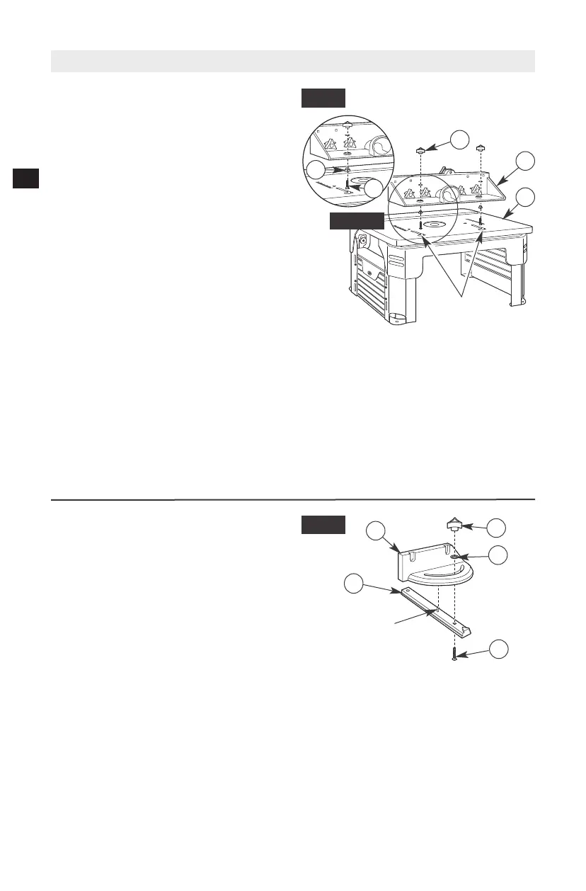
MITER GAUGE ASSEMBLY (Fig. 13)
The miter gauge assembly comes fully
assembled. If not, use the following instructions
to assemble it.
1. Insert tab on top of the miter bar (23) in the
hole in the bottom of the protractor head
(24).
2. Insert the #10-24 x 1" carriage bolt (37)
through the square hole in the miter bar
(23) and slot in the miter gauge and secure
with the flat washer (33) and the small
clamping knob (25).
INSTALLING THE FENCE ASSEMBLY
(Fig. 12 and Detail 12)
The fence comes assembled. Step 1 refers to
reassembly, if necessary; otherwise, go to Step 2
if already assembled.
1. Install spacers (31) on square-head bolts
(47) (Detail 12).
2. From underneath the fence, slide two 1/4-20 x
2
1
⁄
4
" square-head bolts (47) with spacers (31)
up through the holes in the bottom of the
fence assembly (C). Loosely attach a large
clamping knob (21) onto each bolt. (See
Fig. 12.)
3. Insert the square-head bolts (47) with
spacers (31) through the holes of the J-slots
on the tabletop (1), making sure the bolt
heads and spacers are below the inside
surface of the tabletop and can slide freely in
the J-slot.
4. From the rear of the table assembly, slide
the fence assembly (C) right and into the
J-slot and make sure that it slides smoothly
from front to back.
5. Tighten the large clamping knobs (21) to
secure the fence assembly (C) to a desired
position.
NOTE: Use the scale on the tabletop as a guide
when aligning the fence for routing operations.
Once the fence is positioned and aligned
correctly, tighten the clamping knobs SECURELY.
A
C
FIG. 12
37
33
25
23
FIG. 13
TAB
21
47
31
DETAIL 12
24
J-SLOTS
Router removed for clarity