22
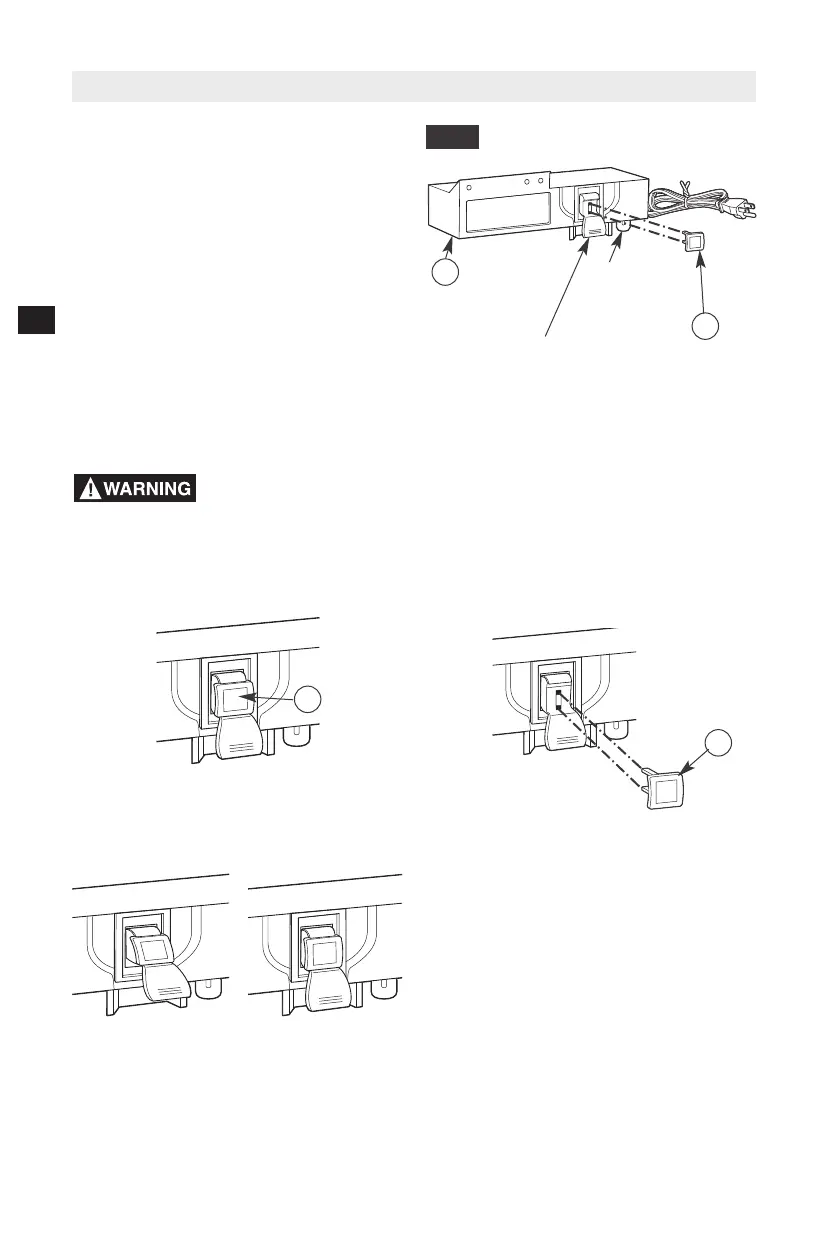
SWITCH OPERATION (Fig. 23)
This section explains the operation and features
of the switch box assembly prior to plugging the
power cord into a power outlet. The intent is to
familiarize the user with the switch operation
without actually turning ON the router.
The switch box (14) (Fig. 23) incorporates a
lockout key (15) to help prevent unauthorized
use by others.
• The lockout key (15) is the yellow part in
the top of the red plastic paddle. The yellow
lockout key must be completely inserted
into the top of the red plastic paddle and
switch box (14) before the paddle can be
turned ON.
• The circuit reset button for the switch box
(14) is on the bottom right side of the box.
Make sure that the
extension cord is not
plugged into an electrical outlet before
proceeding any further.
1. Make sure the yellow lockout key (15) is
completely inserted in the top of the red
plastic paddle.
Yellow
lockout key
Switch box
assembly
Red
plastic paddle
(ON/OFF switch)
FIG. 23
Router Table Operation
4. To prevent unauthorized use, the switch can
be disabled by removing the yellow lockout
key (15) completely from the top of the red
plastic paddle.
2. To turn the router ON, lift the red plastic
paddle up to the ON position.
3. To turn the router OFF, press the red plastic
paddle to the OFF position.
Circuit
reset button
14
15
15
15
OFF
(DOWN)
ON
(UP)