Do you have a question about the Bosch Rexroth IndraDrive HMV01.1E-W0030 and is the answer not in the manual?
Describes the scope and purpose of the documentation for planning mechanical, electrical, and logistical aspects of the equipment.
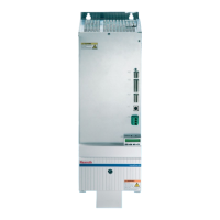
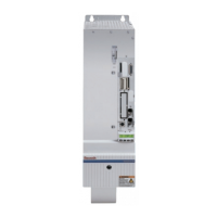
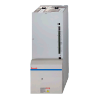
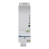
Introduces the supply units, their features, fields of application, basic structure, drive system, and certifications.
Explains the basic structure, control panel, and drive system components of the supply units.
Provides information on CE mark, C-UL-US listing, and relevant test procedures for the supply units.
Defines appropriate use of Rexroth products, emphasizing user responsibility, safety instructions, and product integrity.
Defines inappropriate use of supply units outside specified application areas or conditions, highlighting potential risks.
Covers introductory safety, hazard explanations, general information, and guidance on appropriate and inappropriate use.
Details protection against electric shock from live parts, including PELV and contact with electrical components.
Covers protection against dangerous movements, handling, mounting, and contact with hot parts.
Addresses safety for battery handling and protection against pressurized systems.
Covers packaging, packaging labels, disposal of packaging material, and accompanying documents for delivered components.
Details the standard and optional components included in the delivery and provides instructions for checking the delivered items.
Explains how drive components are identified by type designation, including type plates and cable markers.
Explains device types and the structure of the type code used for identification and configuration.
Specifies conditions for transporting devices, including temperature, humidity, and shock resistance requirements.
Details storage conditions like temperature and humidity, and provides recommendations for long-term storage to maintain component integrity.
Covers ambient and operating conditions for mounting supply units and components into control cabinets, including temperature and humidity.
Explains how duty capacity diminishes with higher ambient temperatures or mounting altitudes, illustrated by diagrams.
Presents mechanical technical data, focusing on dimensions and providing detailed drawings for specific device models.
Recommends vertical installation for cooling and advises on component arrangement in control cabinets for optimal airflow.
Discusses power dissipation of drive systems and components, and the need for cooling units based on heat generated.
Provides instructions and warnings regarding the mounting of cooling units to prevent damage to drive controllers from condensation.
Covers precautions against electrostatic discharge (ESD) and general installation guidelines for wiring and testing.
Discusses interference elimination and Electromagnetic Compatibility (EMC), referencing separate documentation and filter requirements.
Lists 10 essential rules for designing drive systems in compliance with EMC standards, focusing on noise emission control.
Advises on spatial separation of interference-free and susceptible areas for optimal EMC installation in HMV01.1E systems.
Presents detailed electrical data for HMV01.1E-W0030, -W0075, and -W0120 models, including voltage, current, and power specifications.
Provides detailed electrical data for HMV01.1R-W0018, -W0045, and -W0065 models, including voltage, current, and power specifications.
Details the control voltage specifications, including ripple content, overvoltage limits, charging current, and power consumption.
Presents a complete connection diagram illustrating the wiring for various interfaces like X1, X2, X3, X31, X32, X33, and X14.
Explains the overview of connections, including power section, PE connections, and module bus, with designation of components.
Shows the front view of HMV01.1E-W0030 and HMV01.1E-W0075, detailing connections and a table of connection descriptions.
Illustrates the front view of HMV01.1E-W0120, detailing connections and providing a table of connection descriptions.
Shows the front view of HMV01.1R-W0018, -W0045, -W0065, detailing connections and providing a table of connection descriptions.
Details the connection and safety aspects of the control voltage supply, including potential hazards from interruption.
Explains the DC bus connection using contact rails or wires, including design considerations, tightening torque, and wiring requirements.
Illustrates the PE connection for power supply units of different models, specifying screw types and tightening torques.
Details PE connection options for drive controllers, including grounding brackets and cable requirements for safe grounding.
Describes the X1 bus module, its graphic representation, design type, and specifications for extension leads.
Explains the RS232 interface used for diagnosis, detailing its graphic representation, design, and connection cross-sections.
Provides details on the X3 mains connection, including graphic representation, design types for different models, and connection cross-sections.
Details the X31 interface used for messages like 'supply unit ready' and 'power supply ok', including its design and connection cross-sections.
Explains the X32 interface for mains contactor control, DC bus short circuit, and braking resistor threshold signals.
Describes the X33 interface used for acknowledge messages of the internal mains contactor, including its design and connection details.
Details the X14 interface for mains voltage synchronization, available for regenerative supply units (HMV01.1R).
Provides warnings and instructions for mounting the touch guard to prevent lethal electric shock from live parts.
Explains the role of the power supply unit in AC drive systems and the need to determine motors and drive controllers before selection.
Details DC bus continuous power calculation methods, including speed, mechanical power, peak power, and load calculation.
Covers DC bus peak power, regenerated energy, continuous/peak regenerated power, and connected load calculations for unit selection.
Explains control options for mains contactors and DC bus dynamic brakes, including shutdowns due to faults or power failures.
Details control modes using emergency stop relays and DC bus dynamic brake for enhanced safety and fault handling.
Describes operation without DC bus dynamic brake, noting drives shut down via electronics and implications for asynchronous machines.
Explains how NC controller can manage mains contactor for position-controlled shutdown, especially for electronically coupled drives.
Highlights the importance of quick fault localization and replacement due to production downtime, emphasizing modular drive concepts.
Covers fault signaling via display, prerequisites for diagnostics, and methods for resetting stored fault messages.
Requests specific information from users when contacting service personnel for quick and precise assistance with unit checks.
Provides a step-by-step guide for replacing a unit, emphasizing safety precautions, qualified personnel, and checking unit types.
Details product return for disposal, conditions, address, and information on packaging materials and their recyclability.
States products contain no hazardous substances and lists materials in devices and motors, with recycling information.
Provides contact information for helpdesk and service hotlines, including phone numbers and availability outside normal hours.
Directs users to online resources and lists essential information needed before contacting service for efficient support.
Lists sales and service facilities across Germany, categorized by region, with contact details.
Lists sales and service facilities in Western European countries, including contact phone numbers and fax.
Provides contact information for sales and service facilities in Eastern European countries like Czech Republic, Hungary, Poland, Romania, Russia, etc.
Lists sales and service facilities in regions including Australia, China, India, Japan, Korea, Malaysia, Singapore, South Africa, Taiwan, and Thailand.
Provides contact details for Bosch Rexroth North American offices, including headquarters, regional centers, and service hotlines.
Lists sales and service facilities in South American countries such as Argentina, Brazil, and Colombia.
Explains how to correctly connect the supply unit using wires for DC bus connection, avoiding voltage arcing.
Illustrates correct DC bus connections for stacked devices with counterclockwise cable routing, emphasizing prevention of voltage arcing.
Illustrates correct DC bus connections for stacked devices with clockwise cable routing, emphasizing prevention of voltage arcing.
Covers general mains connection guidelines, including direct connection, transformer use, voltage cutoffs, and drop-outs.
Details necessary short-circuit power for mains supply based on connected load and explains mains supply failure tolerance.
Describes the direct mains connection for HMV01.1E power supply units with 3x AC 380-480V, recommending a line filter HFD.
Explains the use of an autotransformer for mains connections with voltages outside the 3x AC 380-480V range for HMV01.1E.
Details the mains connection for HMV01.1R power supply units, requiring a mains choke KDxx and a combining filter HFD.
Discusses the operation and selection of combining filters, including temperature rise calculation and interference suppression.
Presents derating diagrams and formulas for filters, and discusses interference reduction measures for supply lines.
Explains the necessary separate connection for synchronous operation of HMV01.1R with mains, tapping voltage before the choke.
Covers grounding for three-phase systems, protection against overvoltages with IT mains, and the benefit of isolating transformers.
Warns against using RCDs on electric drives and specifies using overcurrent protective devices, explaining leakage current factors.
Discusses the use of earth leakage monitors in IT mains, noting the need for isolating transformers with electronic drive controllers.
Details the chronological sequence of events during power-up, including control voltage, internal routines, and contactor closing times.
Shows the chronological sequence during power-down, including power OFF, acknowledge signal, and contact opening times.
Lists and describes Mains Chokes (KD series) for HMV01.1E, including mechanical, electrical data, and part numbers.
Provides mechanical and electrical data, and part numbers for Mains Chokes (KD series) used with HMV01.1R supply units.
Describes Mains Filter HFD types, features, and usage for interference suppression with IndraDrive M drive controllers.
Lists available filter versions, compatible units, current ratings, and limit values per EN61800-3 for interference suppression.
Provides dimensional drawings for HFD0x.2-480-0065 filter, showing key measurements and connection details.
Presents dimensional drawings for HFD01.2-480-0026 filter, including key measurements and connection information.
Provides dimensional drawings for HFD02.2-480-0026 filter, showing key dimensions and connection details.
Presents dimensional drawings for HFD02.2-480-0202 filter, detailing key dimensions and connection points.
| Brand | Bosch |
|---|---|
| Model | Rexroth IndraDrive HMV01.1E-W0030 |
| Category | Power Supply |
| Language | English |