Do you have a question about the Bosch Rexroth Diax 04 HVE and is the answer not in the manual?
General safety instructions and precautions for installation and operation of the device.
Warnings and safety measures for working with high voltage electrical parts to prevent shock.
Precautions for safe handling and assembly to prevent injury from mechanical hazards.
Causes and examples of dangerous movements from faulty control of connected motors.
Reinforces dangers of uncontrolled movements and measures to prevent accidents.
Health hazards for persons with implants and related precautions.
Warnings about hot surfaces and burn hazards during operation.
Guidelines for intended applications and operating conditions of the product.
Explanation of the structure and meaning of product type codes.
Description of information found on the device's type plate.
Lists the components included with the supply units and accessories.
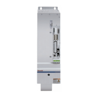
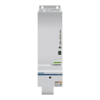
Technical specifications and physical dimensions for HVE models.
Details clearance distances required for HVE installation.
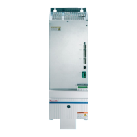
Technical specifications and physical dimensions for HVR models.
Details clearance distances required for HVR installation.
Lists available related documentation for DIAX04 drives and motors.
Requirements for external branch circuit protection.
Wiring diagram for HVE supply units.
Wiring diagram for HVR supply units.
Detailed connection diagram for HVE models.
Detailed connection diagram for HVR models.
Details on the X0 terminal for additional component bus connection.
Information on X1 for bus connections to other devices.
Notes on the X2 interface used for service purposes.
Details on the X3 terminal for emergency stop circuits.
Explains the terminal assignment for the emergency stop circuit (X3).
Provides technical data related to the DC bus.
Information on switching actuations for DC bus brake resistor.
Details on the X4 terminal for control voltages.
Explains the terminal assignment for control voltages (X4).
Instructions for connecting the mains power supply to terminal X5.
Specifics for terminal X5 on HVE04.2 model.
Specifies tightening torques for terminal X5 connections.
Information on X6 for acknowledging the mains contactor status.
Explains the terminal assignment for X6 acknowledging outputs.
Details on X7 for ready-to-operate and warning messages.
Shows terminal assignment for X7 outputs (ready-to-operate, warnings).
Visual representation of terminal assignment for X7.
Explains the function and faults related to the Bb1 contact.
Function of the UD contact for power supply status.
Function of the VW pre-warning contact for cooling unit temperature.
Function of the BVW contact for HVE units related to bleeder power.
Details on the X8 terminal for control voltage supply.
Shows terminal assignment for X8 for HVE and HVR units.
Information on the X11 terminal for DC bus connections.
Guidelines for DC bus connection line length, cross-section, and routing.
Details on the X12 terminal for ground connection.
Information on the X13 terminal for optional choke connection on HVE.
Shows terminal assignment for X13.
Specifies load capacity for X13 connections.
Guidelines for lines connecting to the choke.
General information and precautions for installing the drive controller.
Guidance on sizing control cabinets for multiple-line component arrangements.
Instructions for arranging cooling units to prevent damage.
Measures to prevent moisture condensation in control cabinets.
Procedures and safety measures for discharging DC bus capacitors.
Details on the operating principle and use of the discharging device.
| Brand | Bosch |
|---|---|
| Model | Rexroth Diax 04 HVE |
| Category | Power Supply |
| Language | English |