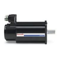
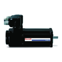
MSK - - - - -050B 0300 NN S1 UG1 NNNN
Frame size
xxx=See project planning manual (e.g. "050")
Frame length
x=See project planning manual (e.g. "C“)
Winding
xxx0=See project planning manual (e.g. "0300")
xxx2=With parameter for field weakening operation (e.g. "0302")
Cooling mode
NN=Natural convection (fan assembly possible from size 060)
FN= Liquid cooling
Encoder
Mx = Multiturn, Sx= Singleturn
x1= Optical, Hiperface, 128 signal periods
x2= Optical, EnDat 2.1, 2,048 signal periods
x3= Capacitive, Hiperface, 16 signal periods
Electrical connection
U= Connector rotatable 240° L= Connector left
A= Connector A-side R= Connector right
B= Connector B-side E, F= Terminal box A-side
Shaft
G= Smooth shaft with shaft sealing ring
P= Shaft with keyway acc. to DIN 68851 with shaft sealing ring
K= Shaft conical with shaft sealing ring
Holding brake
0 = Without holding brake
1, 2, 3= With holding brake (for technical data refer to project planning manual)
Housing design
1) Special product, partially available with further special features ( see product type code)
2) For description see operating instructions "DOK-MOTOR*-MSK*EXGIIK3-IBxx-xx-P"
3) Observe product insert
4) Product information on demand
1
1)
1)
NNNN = Standard
xSxx = Ex design acc. to Device Group II Categories 3G
and 3D acc. to EN 60079 ff
Nxxx = Tolerance DIN 42955-N
Rxxx = Tolerance DIN 42955-R
xPxx = Pump drive
xx01 = Shortened shaft design
xx02 = Shaft conical (JIS 0614, JIS B 0904)
xx35
= Flange or foot assembly (B35)
xxAx
= Vibration resistance increased
xxBx
= Fixed bearing A-side
xxPx = Sealing air connection
xxVx
= Reinforced bearing
xxxK
= Encoder connection 17 pole
2)
1) 2)
1) 4)
1) 4)
1) 4)
1 4)
1) 3)
1) 4)
1)
msk01-0004ts
B
A
L
R
Fig. 4-2: Overview type designation

 Loading...


