M
3
6
8
5
7
1
GNYE
U
PE
PE
Netz
mains
A1
A2
A3
MotTemp
-
M
+24VBr
0VBr
otTemp+
T1 (+)
T2 (-)
L1
L2
L3
V
W
5
6
2
3
PTC
1
PK
2
VT
BK
RD
3
GN
4
BU
5
BN
6
GY
7
WH
8
9
10
BN
B+
B-
EncData-
EncCLK-
EncData+
EncCLK+
A+
A-
-X8
-X6
-X5
-RGS
-RLS
1
2
BD(+)
BD(-)
U1
V1
W1
7
8
9
n.c.
3
4
6
5
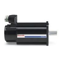
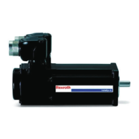
① Motor housing
② Device connector power
③ Device connector encoder
④ Equipotential bonding connection at the motor (only available
on ATEX motors)
⑤ Equipotential bonding connection at the machine (required for
ATEX motors)
⑥ Rexroth drive controller
Fig. 6-3: Connection diagram of device connector
24/57
Assembly
MSK Synchronous Servomotors
Bosch Rexroth AG R911325169_Edition 03

 Loading...


