Connector
size
Pole pattern Device connec‐
tor
Notes
M23
W1
V1
9
8
7
5
6
U1
U1
V1
W1
5
6
7
8
9
A1
A2
A3
PE
MotTemp+
MotTemp-
+24VBr
0VBr
n.c.
RLS1100
1)
RLS1103
Power
M40
U1
W1
V1
9
5
6
8
7
U1
V1
W1
5
6
7
8
9
A1
A2
A3
PE
MotTemp+
MotTemp-
+24VBr
0VBr
n.c.
RLS1200
1)
RLS1203
Power
M58
87
56
9
U1
W1 V1
U1
V1
W1
5
6
7
8
9
A1
A2
A3
PE
MotTemp+
MotTemp-
+24VBr
0VBr
n.c.
RLS1300 Power
M23
1
2
3
4
5
6
7
8
9
10
VCC_Encoder
GND_Encoder
A+
A-
B+
B-
Enc_Data+
Enc_Data-
Enc_CLK+
Enc_CKL-
1
2
3
5
4
6
7
8
9
10
RGS1000
1)
RGS1003
Encoder
M23
E
17
1
16
10
12
13
2
3
4
5
67
8
9
11
1415
1
2
3
4
5
6
7
8
9
10
A+
A-
n.c.
n.c.
VCC_Encoder
n.c.
GND_Encoder
Enc_CLK+
Enc_CLK-
VCC_Encoder
11
12
13
14
15
16
17
B+
B-
n.c.
ENńcData+
n.c.
n.c.
EncData-
RGS1010 Encoder
1) Device connector rotatable
Tab. 6-3: Pin assignment device connector
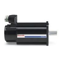
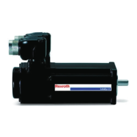
The orientation of the device connector is adjustable. To change the orienta‐
tion, screw a coupling completely onto the device connector. Then move the
device connector with the coupling to the desired position. The adjustment
possibilities are shown in the following figure.
MSK Synchronous Servomotors 25/57
Assembly
R911325169_Edition 03 Bosch Rexroth AG

 Loading...


