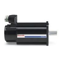
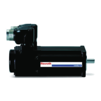
Terminal box type RKL1200, RKL1300
①⑤ Screw connection
② O-ring
③ Adapter plate to accommodate the screw connection
④ Reduction (optional for cable cross-sections 1.5, 2.5 mm²)
⑥ Adapter plate mounting screws
⑦ Cover screws
⑧ Cover
⑧ Seal of terminal box cover
Fig. 6-9: Assembly RKL1200, RKL1300
The power connection is made in single or double wiring. The assembled
power cables are inserted into the terminal box via the adapter plates (2 ×
M40×1.5) and cable glands.
Power cable connection at the ter‐
minal box
Connecting the power cable to the terminal box requires the following steps:
1. Open the terminal box cover.
Loosen and remove the mounting screws (4 pieces).
2. Remove the protective cover of the cable gland.
3. Detach the adapter plate ③ from the terminal box.
4. Screw the adapter plate firmly to the metric cable gland on the power
cable. Use reduction for power core cross-sections of 1.5 mm² and
2.5 mm².
Before attaching the power cable to the adapter plate, check the correct
condition and position of the O-ring.
5. Feed the power cable up to the adapter plate through the opening in the
terminal box and fasten the adapter plate to the terminal box.
Tightening torque of the screws ⑥: 9 Nm (±10%)
30/57
Assembly
MSK Synchronous Servomotors
Bosch Rexroth AG R911325169_Edition 03

 Loading...


