M
3
1
7
8
6
U1-2
5
1
1
GNYE
GNYE
U1-1
PE
F 1
PE
PE
Netz
mains
A1
A2
A3
MotTemp-
MotTemp+
0VBr
+24VBr
1TP1 (+)
1TP2 (-)
BD(+)
2TP2 (-)
2TP1 (+)
L1
L2
L3
V1-2
W1-2
V1-1
W1-1
2
3
4
5
6
BD (-)
2
3
2
3
F 1
PTC
PTC
-X5
-X6
5
4
3
1
2
6
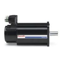
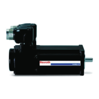
① Motor housing
② Terminal box
③ Holding brake (option)
④ Equipotential bonding connection at the motor (only available
on ATEX motors)
⑤ Equipotential bonding connection at the machine (required for
ATEX motors)
⑥ Rexroth drive controller
Fig. 6-12: Connection diagram terminal box double wiring RLK1300
● Fuses F1 (NH...) protecting the wires against overload in
case of a cable break must be dimensioned according to the
current carrying capacity of the particular line cross-section.
● The fuses should be installed in the control cabinet such that
they are as close as possible to the power output of the con‐
troller.
● The shield of the motor power cable must be connected to
the control cabinet on the motor side of the fuses such that it
is conducting over a large area.
● Power cables are not available to establish the double ca‐
bling. To install the fuses, standard Rexroth power cables
have to be opened and cut to the appropriate length on site.
MSK Synchronous Servomotors 33/57
Assembly
R911325169_Edition 03 Bosch Rexroth AG

 Loading...


