14/16 Assembly description
Bosch Rexroth AG, SB23, SB33, EHR23, EHR33, RE 66133-10-R/05.2013
5.6 Coupling flange seals repair
The coupling connections are customer-specific and differ from the presentation.
Table 6: Coupling flange seals
Item Quantity Designation Use Information
2 O-ring Port A, B 18 x 2.5
2 Support ring Port A, B 24.5 x 2.15
1. Dismount the customer-specific coupling connection according to the vehicle
manufacturer’s instructions.
2. Remove the O-rings and the support rings from the working ports A and B.
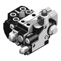
Fig. 12: Coupling disassembly
1. Insert the O-rings and support rings into the port A and B.
2. Assemble the coupling flange according to the vehicle manufacturer’s
instructions.
3. Tighten the mounting screws clockwise applying a torque according to Table 7.
Table 7: Tightening torques mounting screws
Screw M6 M8
Oiled
11
+1
Nm 20
+3
Nm
Fig. 13: Assembly of the customer-specific coupling flange
Coupling disassembly
Assembly of the customer-
specific coupling flange
 Loading...


