22/88 Bosch Rexroth AG SE352/SE352M | 3 609 929 B61/2008-09
B-slot interface (B1) (SE352M)
This interface is intended for use of type B
interface modules from Rexroth.
The slot can be equipped with any of the
following modules:
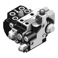
LED and reset bu tton
There are four LEDs on the front panel of the
control unit, which indicate the operating
conditions of tightening channels 1 and 2.
Fig. 2:
* Possible causes: Sequence test, nutrunner in bypass
The reset button can be used to reset the
hardware. For further information, please
refer to chapter “9 Maintenance and repair”
on page 26.
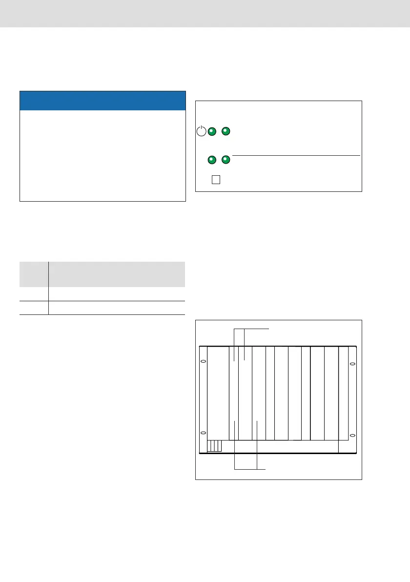
The assignment of the servo amplifiers to the
tightening channels is shown in Fig. 3:
Fig. 3: Tightening channel assignment
ATTENTION
Damage due to improper assembly!
Damage to the connections
y Carefully insert the modules following
the assembly instructions in the module
operating instructions.
y Only use interface modules from
Rexroth.
Tab. 1:
Mod-
ule
Description Order
number
IM24V 24 V inputs/outputs 0 608 830 259
IMser Serial 0 608 830 260
LED
Green Ready for operation
Green, flashing Not ready for opera-
tion, but no system
error
Red, flashing System error
LED Green Tightening result OK
Red, flashing Tightening result NOK
Button Reset
✔
12
SE LT LT
Tightening channel 1
Tightening channel 2

 Loading...