© 2004 Bosch Security Systems
130 Perinton Parkway, Fairport, New York, USA 14450-9199
Customer Service: (800) 289-0096; Technical Support: (888) 886-6189
03/04
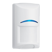
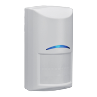
RF940E Installation Instructions
P/N: 42722G Page 2
5.0 Battery Installation
The batteries are not installed in the detector when it is shipped.
When installing the batteries it is necessary to observe proper polarity
or the sensor may not function. When the batteries are installed, wait
at least 5 minutes before activating the Walk Test Mode. The LED will
stop flashing when the detector is ready to test (the sensor requires
"lack of motion" to stabilize on startup).
6.0 Walk Testing
NOTE: Mount the detector between 2.3 m and 2.7 m high and consult
the following pattern drawings:
Lens Patterns
Broad Coverage - Standard on the RF940E
6
6
12
0
Meters
0
1
2
3
4
5
6
7
8
9
10
11
0
12
3
Meters
2.3
0
Look
Down
67-
77
56-
66
45-
55
34-
44
23-
33
12-
22
1-
11
Top View
Side View
Pattern Testing
Remove and replace cover to activate a 90 second Walk Test
Mode. During this Test Mode, any activity in the sensor’s coverage
pattern will cause a transmitted alarm and LED activation. Each
alarm will also extend the Test Mode for an additional 90 seconds.
Walk Testing should be done across the coverage pattern. The
edge of the coverage pattern is determined by the first flash of the
LED. This may change slightly depending upon the sensitivity
setting. Walk Test the unit from both directions to determine the
pattern boundaries.
Although generally not required, if
masking is desired, the lens diagram
shows the appropriate areas to be
masked. Use an opaque material (such
as, electrical tape) to mask the desired
areas.
NOTE: Excessive use of the Walk Test
Mode may reduce battery life.
Use only for initial setup and
maintenance testing.
Final Testing
While the detector is in the Walk Test Mode, turn on all heating and air
conditioning sources which would normally be active during the
protection period. Stand away from the sensor and outside the
coverage pattern and watch for alarms.
After setup and tests are completed, and there has been no activity
in the sensor’s coverage pattern for approximately 90 seconds, the
LED will flash to indicate that the Walk Test mode is ending.
NOTE: In the normal operating mode, an alarm can be transmit-
ted only after three (3) minutes have passed since the
previous alarm restoral. This 3 minute lockout time
reduces unnecessary RF transmissions in high traffic
areas thereby extending battery life.
Maintenance
At least once a year, the range and coverage should be verified for
proper operation. To assure daily operation, the end user should
be instructed to walk through the far end of the coverage pattern to
verify an alarm output prior to arming the system.
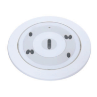
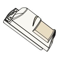
• Align the detector base over the magnet as shown below:
Wall Tamper
Magnet
Location
• For Corner Mounting:
Top View
10 mm
Corner Mounting
65 mm
10 mm
9 mm
Top of Base
• Do not mount the magnet
flush with the wall. A
small amount of adhe-
sive is recommended to
keep the magnet in
place.
• Set the Wall Tamper jumper.
Wall
Tamper
No
Tamper
4.0 Programming your Control/Communicator Panel
There is a two part ID sticker located on the back of the cover of the
RF940E. You will need the number off this sticker to program this
device into the system.
167770187
167770187
ID Number
See your Panel's Wireless Reference Guide for programming
information for wireless-type devices.
1 234567891011
12 22
23 33
34 44
45 55
56 66
67 77
RF940E Lens
(inside view)
 Loading...