• Remove the detector’s cover using a small flatblade screwdriver.
Bottom of Detector
Insert screwdriver here or here
• Remove the board from the case by pressing the mounting tabs
toward the side of the case and gently lifting the board.
• Punch out appropriate holes in the mounting plate (for surface
or corner applications). For optional swivel mount bracket, see
instructions that come with the bracket.
NOTE: To avoid possible circuit board damage, use only the
mounting hardware provided in the appropriate punch-out
mounting holes.
•
In non-pet applications only, if look-down is desired, peel away
the look-down mask. Do not remove the clear plastic lens.
• Mount the detector between 2.3 m and 2.7 m high.
If wall tamper is desired:
• Determine the location of the detector. Measure 65 mm from the
center of the detector and mark the spot on the wall. Drill a 9 mm
hole in the wall.
• For Surface Mounting:
Surface Mounting
9 mm
65 mm
• Tap the magnet into the wall.
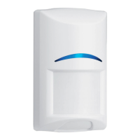
Installation Instructions
for the RF940E
Passive Infrared Detector
1.0 General Information
The RF940E is a high performance PIR Motion Sensor which uses
advanced signal processing to provide outstanding catch
performance and unsurpassed false alarm immunity. With Bosch
Security Systems Pet Friendly
®
pet immunity, the RF940E will not
detect a dog up to 13kg, two cats, and numerous rodents. It contains
an integral RF transmitter capable of transmitting 300 meters in
open air. (Actual acceptable transmitter range should be verified for
each installation). The transmitter sends a battery report with each
transmission and transmits a supervisory signal to the control panel
every 13 minutes.
2.0 Specifications
• Dimensions (H x W x D): 7.6 cm x 5.7 cm x 3.8 cm
• Coverage Area: 12 m x 12 m
• Operating Temperature: 0° to +49°C. 0 to 95% relative
humidity noncondensing.
• Frequency Band: 433.42 MHz
• Maximum RF Power: Less than 10 mW
• Operating Voltage: Supplied by two 3 VDC lithium
batteries
• Battery Life: Approximately 5 years under
normal operating conditions using
the recommended battery types.
• Recommended Battery
Types: Duracell DL123A,
Energizer EL123AP, or
Panasonic CR123A.
• Compatible Receivers: RF3212E, RF3222E, or RF3224E
• Compliance: CE 0165 - this device complies
with EN 300683, EN 300220, and
89/336/EEC
• Options: B335 Low Profile Swivel Mount
Bracket (The use of brackets may
reduce range and increase dead
zone areas)
3.0 Mounting Procedure
Surface or Corner Mounting (without swivel bracket)
• The maximum wireless range of the detector, in open air, is
approximately 300 meters. In normal household or commercial
applications it is recommended that the detector be kept within
100 meters of the control panel receiver to which it is assigned.
It is recommended that the detector be temporarily mounted, using
double sided tape, and tested for both detector coverage and RF
range from the desired location before permanent mounting.
• Mount the detector where an intruder will most likely cross through
the coverage pattern.
• Do not mount in areas with large metallic surfaces (e.g. heating
ducts) or electrical wiring which may inhibit the sensor’s RF signals
from reaching the Control Panel Receiver.
• Do not mount the detector outdoors or where direct sunlight can
reach it.
• In pet immune applications, do not mount where pets can climb
because the upper areas are not pet immune.
Don't overtighten the mounting screws
Cover may not attach correctly
Corner Mount
Surface
Mount
Mounting
Ta bs
Remove
Areas
if using the
B335 Bracket