12 | Εlectric water heater EN
I. Purpose of use
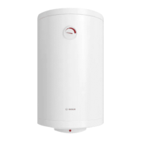
The appliance is designed to supply
hot water to household facilities
equipped with a piping system operat-
ing with pressure not greater than 7
bars (0,7 Mpa). The appliance is de-
signed to function in closed, heated
premises and is not designed to oper-
ate at constant flow regime.
II. Technical specifications
1. Nominal volume V, liters - see the
appliance’s rating plate
2. Nominal voltage - see the appli-
ance’s rating plate
3. Nominal power consumption - see
the appliance’s rating plate
4. Nominal pressure - see the appli-
ance’s rating plate
5. Water heater type - closed accumu-
lating water heater, with thermal in-
sulation
6. Inner coating: GC-glass-ceramics
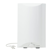
III. Description and principle of
operation
The appliance consists of a body,
flange, plastic control panel, safety re-
turn valve.
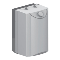
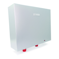
1. The body consists of a steel reservoir
(water tank) and plastic housing
(outer shell) with thermal insulation
placed in-between, and two pipes
with thread G ½“, for cold water sup-
ply (marked with a blue ring) and hot
water discharge (marked with a red
ring).
The inner reservoir is made of steel
proved against corrosion by a special
glass-ceramic coating.
2. The flange is fitted with electric heat-
er and magnesium anode protector.
The flange is fixed to the water tank
with bolts.
The electric heater heats the water in
the tank and is controlled by the
thermostat, which automatically
maintains the preset temperature.
The plastic control panel incorporates:
switch (depending on model), ad-
justable thermostat (depending on
model), and thermal cut-out and
control lamps.
The thermal cut-out is a device, which
switches the heater off the power
supply when the water temperature
reaches excessive values. If this de-
vice is actuated, you should call a
service station.
The signal lamps (depending on model)
on the control panel indicate the cur-
rent mode of the unit.
The magnesium protector provides ad-
ditional anti-corrosion protection to
the internal tank for heaters fitted
with glass-ceramic coating.
3. The safety-return valve prevents the
appliance’s complete emptying in
the event of cold water supply inter-
ruption. The valve protects the appli-
ance from pressure increases higher
than the allowed value(8 bar/0,8MPa)
during heating (! pressure will in-
crease when temperature increas-
es), by releasing the excess pressure
through the drain outlet. Water drop-
ping out through the drains during
the warming process is a normal
event that must be taken into consid-
eration when the boiler is installed.
ATTENTION! The safety-return valve
cannot protect the appliance from
water supply pressure exceeding the
pressure indicated for the appliance.
In the event of higher water supply
pressure there will be constant leaks
from the appliance drains.

 Loading...