EN Εlectric water heater | 13
IV. Installation and switch on
ATTENTION! Qualified technicians
must perform all technical and elec-
trical assembly works. Certified
technician is the person who pos-
sesses the relevant competence in
accordance with the legislation of
the respective country.
1. Installation
We recommend installation of the de-
vice at close proximity to locations
where hot water is used, in order to
reduce heat losses during water trans-
portation. The selected location must
exclude the possibility of water spray
originating from the showerhead or
other water contacts.
The appliance is affixed to a wall by
means of mounting brackets attached
to the unit’s body. Two hooks are used
to fix the appliance (min. Ø 6 mm)
firmly on the wall (included in the
mounting set). The bearing plank con-
struction for boilers installed above /
under sinks is universal and allows the
space between hooks to vary between
96 and 114mm. (fig.1)
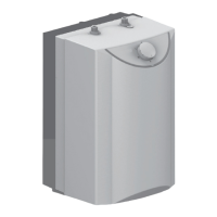
IMPORTANT: The type of boiler de-
signed to be installed UNDER /
ABOVE a sink is marked on the appli-
ance. Boilers designed for installa-
tion above sinks are assembled in
such a manner that the outlet/inlet
pipes are pointed downwards (to the
floor of the premise). Boilers de-
signed for installation under sinks
are assembled in such a manner that
the outlet/inlet pipes are pointed up-
wards (to the ceiling of the premise).
For clear understanding of wall instal-
lation schemes, please refer to fig.2 (A
above sink and B under sink).
ATTENTION! In order to prevent inju-
ry to user and third persons in the
event of faults in the hot water sup-
ply system, the appliance must be
mounted in premises outfitted with
floor hydro insulation and sewer
drainage. Don't place objects, which
are not waterproof under the appli-
ance under any circumstances. In the
event of mounting the appliance in
premises without floor hydro insula-
tion, a protective tank with a sewer
discharge drainage must be placed
under the appliance. Notice: the set
does not include a protective tank, it
must be selected by the client.
2. Water heater connection to
the water supply system
Fig.4a – installation scheme above sink
Fig.4b – installation scheme under sink
Where: 1 – input pipe, 2 – safety valve
(0.8 MPa), 3 – reduction valve (if the wa-
ter supply pressure exceeds 0,7 MPa), 4
– stop valve, 5 – bell-mouth discharge to
the sewer, 6 – hose; 7 - Drain water tap.
Upon connecting the water heater to the
water supply system, take care of the in-
dicative color markings /rings/ of the
pipes:
BLUE - for cold /in-flowing/ water
RED - for hot /out-flowig/ water.
The mounting of the safety return-valve
supplied with the water heater is obliga-
tory. The safety return-valve must be in-
stalled on the cold water supply pipe, ac-
cording to the arrow stamped on its body
that indicates the supplied water direc-
tion. Additional stopcocks must not be

 Loading...
