EN Εlectric water heater | 15
cord.
The connection of the water heater to
the electrical network is carried out
via a power cable with three leads
3x1.5 sq mm through a separate cir-
cuit, protected by a 16-amp fuse.
Switch device having contact sepa-
ration in all poles that provide full
disconnection under overvoltage
category III conditions must be in-
corporated in the fixed wiring in ac-
cordance with wiring rules.
In order to fix the power cable to the
water heater, it is necessary to re-
move the plastic cover (fig.5). The
power leads connections must be in
accordance with the terminal mark-
ings of the thermal circuit breaker:
- the phase cable must be connected
to the A1 (11) terminal
- the neutral, to the B1 (21) terminal,
- and the protection terminal, obliga-
tory to the marked screwed joint
.
The power supply cord can be fixed to
the plastic control panel with a ca-
ble stop. After the installation, the
plastic cover must be replaced in its
original position!
Explanations to Fig.3:
T1 – thermal regulator, T2 – thermal
circuit breaker, S – electrical switch
(for models that have one), IL1 and
IL2 – signal lamp, R – heater.
V. Operation
When you have performed the instruc-
tions described in Item IV above, you
can start using the appliance.
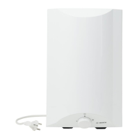
The appliance has two indicating
lamps (fig.6). Lamp (1) is on when the
appliance is connected to the power
supply and indicates that voltage is
supplied to it. Lamp (2) is on when the
boiler is switched on in water heating
mode. Lamp (2) switches off when the
water reaches the preset temperature
and indicates that the appliance is not
in operation.
Electrical switch (3) positions (for
models with switch):
- Position 0: switched off - the heater
is off and the boiler does not heat the
water
- Position I: the heater is on and the
water heating is automatically regulat-
ed by the thermostat
Positions of the thermostat control
knob(4) (for models that have one):
- Anti-Frost Position the thermostat is
set to minimum level of water heating.
In this mode, the boiler switches on
when the temperature of the water
contained in the water reservoir falls
under 5oC. It is suitable in cases of po-
tential low temperature of the water
contained in the water network.
- Position I (Summer Mode) the ther-
mostat is set to economical mode of
operation for low water temperature
and low power consumption. This
mode is suitable for summer condi-
tions, when no high water temperature
is not needed.
- Position II (Winter Mode) the ther-
mostat is set to optimum operation
mode, with higher water temperature
values. This mode is suitable for au-
tumn and winter conditions, when
higher water temperature is needed.
- Position III (Maximum Mode) the
thermostat is set at maximum opera-
tion mode and power consumption,
with highest water temperature level
(about 70°C). This is the most suitable
 Loading...