EasyManuals Logo

Bosch VG4 Series Installation Guide

Bosch VG4 Series
20 pages
To Next Page IconTo Next Page
To Previous Page IconTo Previous Page
Page #13 background imageLoading...
Page #13 background image
Fiber Optic Media Converter Installing the Fiber Optic Module | en 9
Bosch Security Systems, Inc. Installation Guide F.01U.134.924 | 1.0 | 2009.09
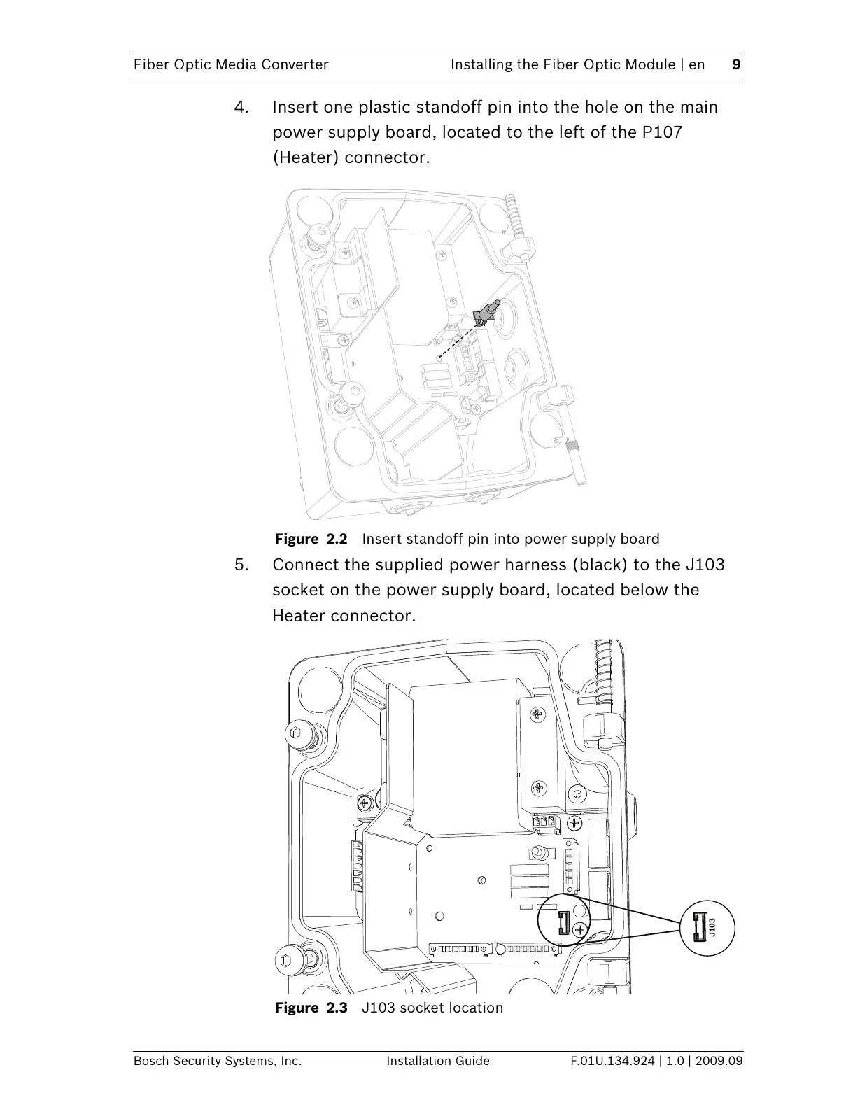
4. Insert one plastic standoff pin into the hole on the main
power supply board, located to the left of the P107
(Heater) connector.
Figure 2.2 Insert standoff pin into power supply board
5. Connect the supplied power harness (black) to the J103
socket on the power supply board, located below the
Heater connector.
Figure 2.3 J103 socket location
J103
All manuals and user guides at all-guides.com

Other manuals for Bosch VG4 Series

Questions and Answers:

Question and Answer IconNeed help?

Do you have a question about the Bosch VG4 Series and is the answer not in the manual?

Bosch VG4 Series Specifications

General IconGeneral
Weatherproof RatingIP66
Pan Range360° continuous
CommunicationRS-485
Lens TypeVarifocal
Day/NightYes
Power12V DC

Related product manuals