2. 6. Controls
2.6.1. Control knob for switching the appliance On or Off.
2.6.2. Control knobs for adjusting the CH or DHW temperatures.
2.6.3. CH control knob switches the CH off and on.
2.6.4. A programmable room thermostat or a facia mounted
programmer or clock is available.
2.6.5. A radio frequency room thermostat is available.
2.6.6. A mains voltage room thermostat and/or an externally
mounted mains voltage programmer may be connected to the
appliance.
2.7.
System
2.7.1. All dirt must be flushed from the system before connecting
the appliance.
2.7.2. The connections in the system must withstand a pressure
of upto 3bar.
2.7.3. Radiator valves must conform to BS2767:10:1977.
2.7.4. Table 3 gives the pump head available for the system and
the required temperature differential.
2.7.5. A drain cock must be fitted to the lowest point of the
system.
2.7.6. An air vent should be fitted to the highest point of the
system.
2.8.
Showers, Bidets, Taps and Mixing Valves
2.8.1. All taps and mixing valves must be suitable for the
available mains pressure and temperatures upto 65°C. It may be
necessary to fit a pressure reducing valve.
2.8.2. Hot and cold mains fed water can be supplied to overrim
bidets but is subject to local water company requirements.
2.8.3. The flow of water from individual outlets varies on all
mains fed systems that are not fitted with flow balancing valves.
2.8.4. If a pressure equalising valve is fitted then the domestic
hot water temperature should be set to maximum.
2.8.5. Thermostatically controlled shower valves give extra
comfort and protection.
2.9.
Safety
2.9.1. The appliance must not be operated with the inner casing
cover removed.
2.9.2. The gas and electricity supplies must be turned off before
servicing or working on the appliance.
2.9.3. A water system low pressure (0.45 bar) cut-off switch is
fitted.
2.9.4. Temperature monitoring controls are fitted to prevent
overheating.
2.9.5. Automatic frost protection is provided which will protect
the appliance when no heat demand is present.
2.9.6. Automatic pump seizure protection is provided.
2.9.7. The gas valve solenoids are successively and alternately
closed to check for gas tightness by reference to the flame cut-off
time.
2.10.
Operation
2.10.1. Central Heating:
A demand for heat will ignite the burner and it will operate at
minimum pressure for 2 minutes before increasing to the
maximum over a period of 1 minute and then automatically
match the system requirements. At the end of the demand the
burner will go out and the pump will continue to run for upto 4
minutes or the fan for 15 seconds. There is an anti-cycle time of 3
minutes.
2.10.2. Domestic Hot Water:
A demand for hot water will light the burner with the pressure
rising to maximum over a period of 4 seconds. At the end of the
demand the fan will continue to run for 15 seconds if neither
pump is operating. There is an anti-cycle time of 10 seconds.
The demand for hot water will override the CH function for the
period of the hot water demand. In winter when the inlet water
temperature is very low it will be necessary to reduce the flow at
the taps to maintain the delivery temperature.
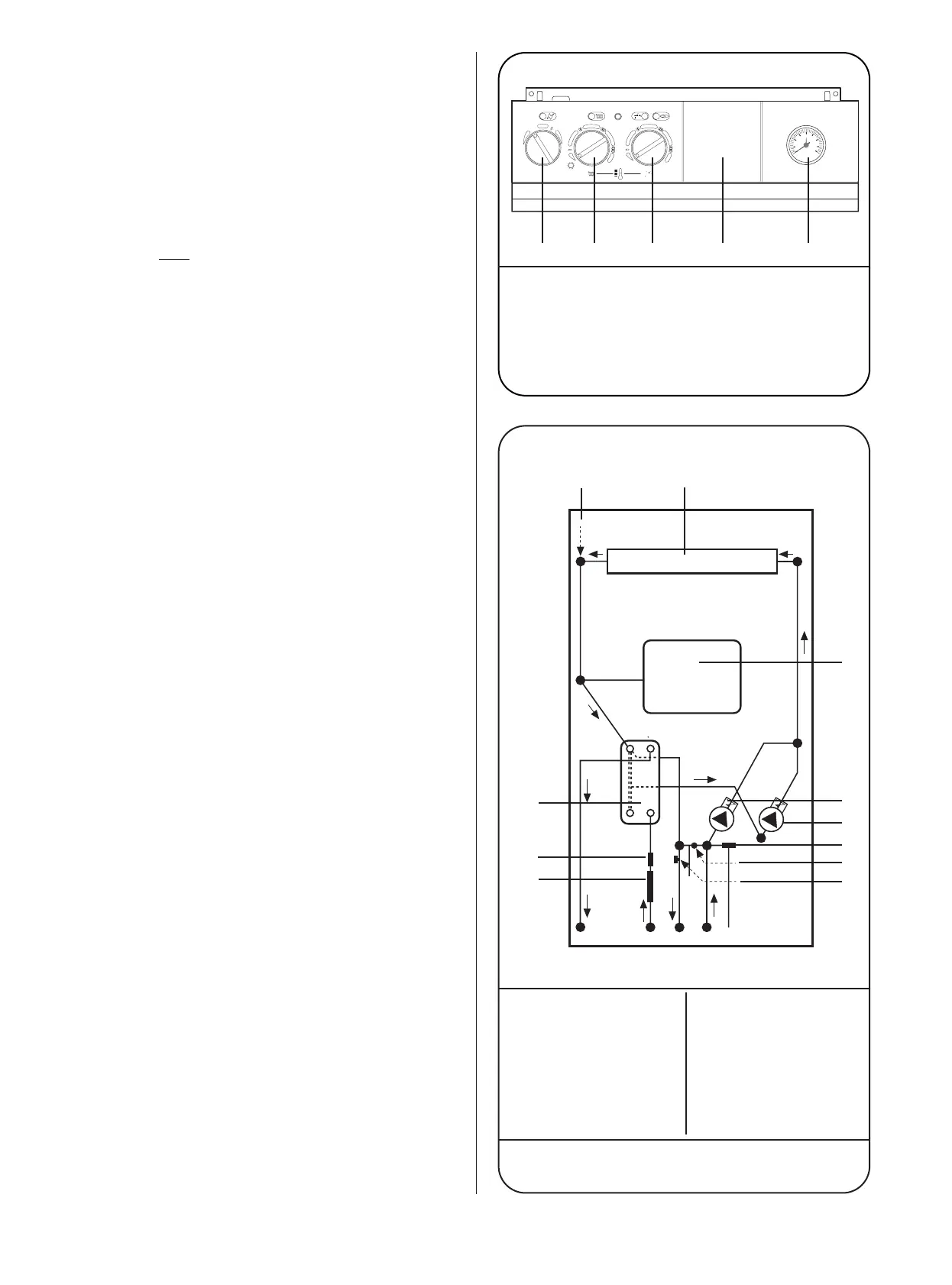
1. Mains ON/OFF Control Knob
2. Central Heating Temperature Control Knob and CH ON/OFF
Control
3. Domestic Hot Water Temperature Control Knob
4. Programmer/Clock Position - (Optional)
5. System Pressure Gauge
1. Primary Heat Exchanger 7. System Pressure Switch
2. Sealed System Expansion 8. Water Flow Regulator
Vessel
3. Central Heating Pump 9. Flow Switch
4. Domestic Hot Water 10. Domestic Hot Water Heat
Pump Exchanger
5. Relief Valve
1
1. Primary Flow Manifold
6. Bypass Adjuster
A. Domestic Hot Water Flow C. Central Heating Flow
B. Cold Water In D. Central Heating Return
3
MAX. MAX.MIN.