Commissioning
Greenstar Danesmoor Kitchen
ErP+
and Kitchen System
ErP+
-6 720 821 686 (2018/04)44
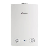
6.4.6 Combustion checks
▶ Start and run the boiler for 20 minutes.
▶ Remove the sampling point plug [1] to check the smoke reading is
between 0-1. If the smoke level is above 1, check the combustion
settings are correct and the oil nozzle is in good condition.
Fig. 74
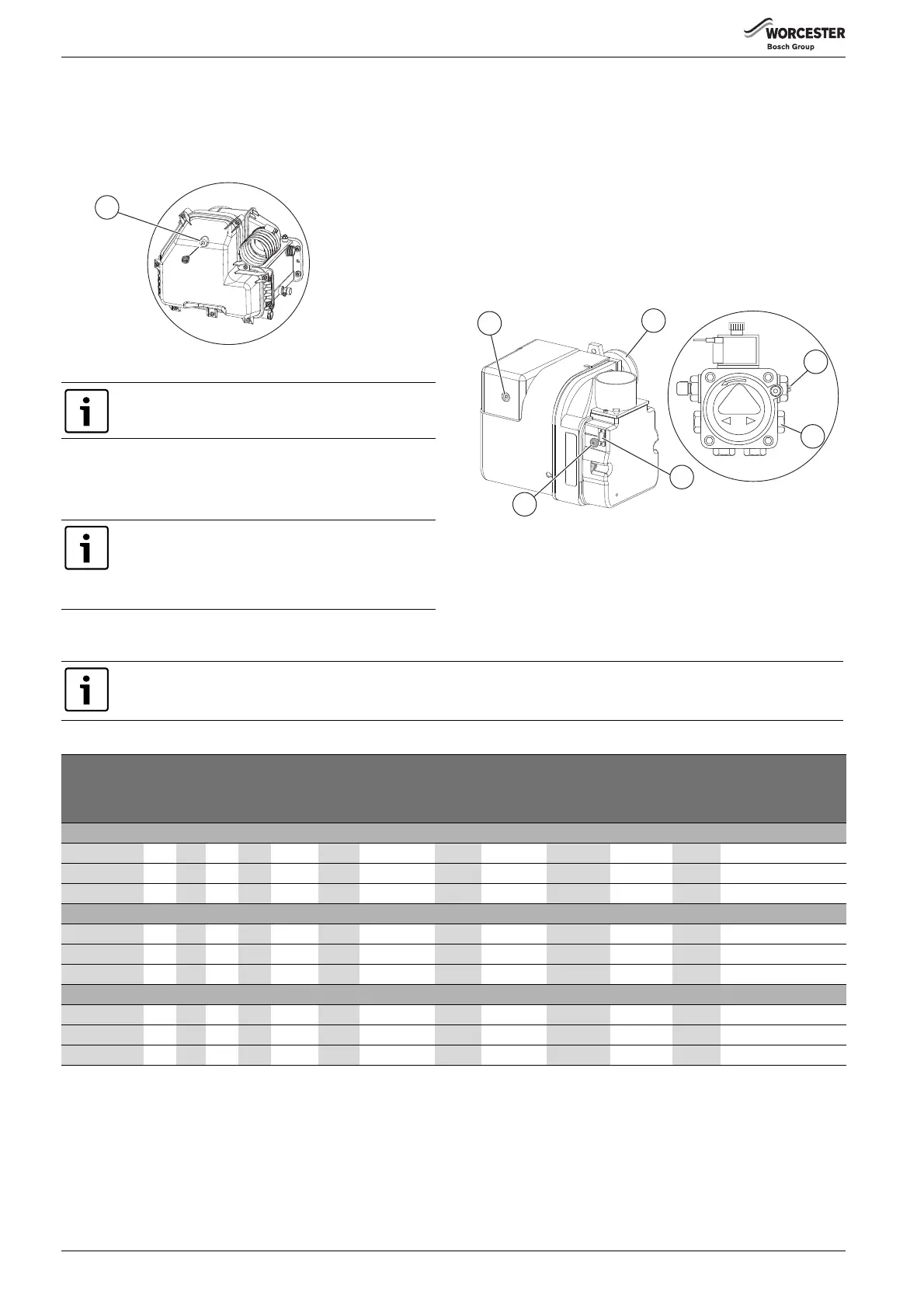
▶Check the CO
2
levels and adjust the air shutter [6] figure 75 setting
according to the table opposite.
▶ Check the flue gas temperature is close to the values shown in the
table 10 on page 44.
▶ Turn off the electrical supply.
▶ Isolate the oil supply to the burner.
▶ Remove the oil pressure gauge.
▶ Refit the blanking plug [4] figure 75.
▶ Check and rectify any oil leaks.
▶ Switch on the oil supply.
▶ Switch on the electrical supply.
▶ Restart the boiler and run for five minutes.
▶ Recheck the CO
2
levels and if required, adjust the air shutter setting
[6] figure 75 to obtain the correct CO
2
level.
▶ Refit the sample point cap (hand tighten only, do not over tighten)
and refit the burner cover.
Fig. 75
[1] Lockout feset button
[2] Combustion head
[3] Pressure adjustment
[4] Bleed and pressure gauge port
[5] Air shutter display window
[6] Air shutter adjuster
Nominal boiler rating at normal operating temperature using Kerosene (Class C2)
Smoke readings may be inaccurate until the smoke from
the burning organic binder in the access door insulation
has ceased.
If the flue gas temperature is too high and the baffles are
correctly fitted, then reduce the oil pump pressure [3]
fig. 75, 5-10 p.s.i. to compensate for nozzle variations.
If the pump pressure has been changed, the CO2 levels
must be rechecked and air shutter adjusted if necessary.
6720809437-35.1Wo
1
APPLIANCE MUST BE SET TO CO
2
LEVELS.
AIR SETTINGS GIVEN ARE APPROXIMATE ONLY, AS FLUE LENGTH AND NOZZLE VARIATIONS WILL AFFECT THIS.
Oil pump
pressure
Fuel flow
rate
Approx
flue gas
temp.
Combustion
head settings
Approx.
air
setting
Input
(appliance)
Output
(appliance)
Air damper
disc
setting
Flue
damper
required
Burner head
Nozzle bar psi Kg/h l/h °C %CO2 mm kW kW
Greenstar Danesmoor 12/18 model
0.40 x 80° EH
8.5 123 1.12 1.38 67 12.0 10.5 2.3 13.2 13.0 A Yes BX & recirculation tube
0.40 x 80° EH
10.0 145 1.30 1.60 70 11.5 11 1.75 15.3 15 B Yes BX & recirculation tube
0.50 x 80° EH
10.0 145 1.54 1.90 80 12.0 11.5 2.5 18.3 18.0 C Yes BX & recirculation tube
Greenstar Danesmoor 18/25 model
0.50 x 80° EH
10.0 145 1.54 1.90 76 12.5 12.5 1.5 18.3 18.0 N/A Yes BX
0.60 x 60° EH
8.8 128 1.84 2.28 81 12.5 14 3.25 21.9 21.5 N/A Yes BX
0.65 x 80° EH
9.5 138 2.15 2.66 90 12.5 15 3.25 25.5 25.0 N/A Yes BX
Greenstar Danesmoor 25/32 model
0.65 x 80° EH
9.8 142 2.15 2.66 79 11.5 19 3.5 25.5 25.0 N/A No BX
0.75 x 80° EH
10.3 150 2.46 3.04 84 12.0 19 4.25 29.1 28.5 N/A No BX
0.85 x 80° EH
10.0 145 2.78 3.44 85 12.5 19 4.75 32.7 32.0 N/A Yes
1)
1) Internal boilers with flues less than 4 metres
BX
Table 10 Combustion settings

 Loading...