.3 $ /
PRO.BOSE.COM 3 OF 5
TECHNICAL DATA
PowerShare PS604A
adaptable power amplifier
PROFESSIONAL
.
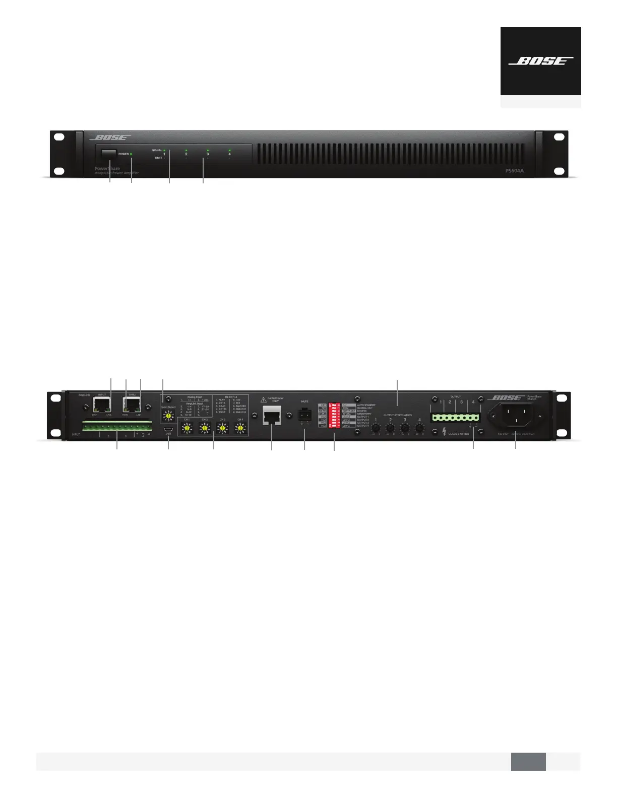
AmpLink – INPUT RJ-45 connector that receives up to 24
digital channels from a Bose AmpLink product. The amp also
supports a THRU path for daisy-chaining all 24 digital audio
channels to other Bose AmpLink products, at a maximum
distance of 10 m between products.
CAUTION: Shielded EIA/TIA 568B straight CAT 5 cable, or equivalent, is required
for proper AmpLink operation. Unshielded cable is not supported and may cause
AmpLink to operate improperly. Do NOT connect either RJ-45 port to an
Ethernet-based network.
3 AmpLink ERR LED – Solid yellow indicates muted audio from
the mute connector. Blinking yellow indicates an error, which
will also mute the audio.
$AmpLink LNK LED – Solid green indicates normal operation
/ANALOG INPUTS – Balanced 12-pin Euroblock line-level input
connector.
1INPUT SELECT – Dial selects if analog or AmpLink audio
inputs are used. The default state is analog 1:1.
4
MICRO-USB – Connect the amplifier to a PC using a USB
connection. This allows you to use the PC-based PowerShare
Editor software to configure the advanced features of the
amplifier.
.
POWER SWITCH – ON/OFF AC power.
3
POWER LED
• Solid green LED indicates the unit is ON.
• Blinking green LED indicates the unit is in low-power mode.
• Solid amber LED indicates an over-temperature fault.
• Solid red LED indicates a power supply fault.
$
INPUT 1, 2, 3, 4 SIGNAL LED – Each LED operates
independently.
• Green LED indicates signal is present.
• Amber LED indicates signal is near clipping.
• Red LED inciates clipping.
• LEDs will display solid red if a power supply fault
is detected.
/
OUTPUT 1, 2, 3, 4 LIMIT LED – Each LED operates
independently.
• LED is amber when the amplifier is limiting the
corresponding output due to exceeding the specified
loudspeaker Vpeak or Vrms limits.
• If the sum of the amplifier outputs exceeds 600 watts, then
the amplifier will limit all outputs equally, and all LEDs will
show limiting simultaneously.
• LEDs will display solid red if an amplifier, power supply, or
EHF fault is detected.
• LEDs will blink red when all outputs are muted.
2
CHANNEL 1, 2, 3, 4 EQ – Each dial provides loudspeaker
equalization presets per channel: DS 16, DS 40, DS 100,
FS3B, 402, 802, MA12EX, RMU105, and RMU108. Use the Flat
setting for FS3 Systems.
(
CONTROLCENTER – RJ-45 input connector for Bose CC-1
ControlCenter zone controllers or CV41 4-to-1 converter only.
,
MUTE – Contact closure connection where a short across the
mute connector will mute all outputs. Mute polarity can be
inverted with the PowerShare Editor software.
"
DIP SWITCHES – A bank of switches used to set amplifier
configuration.
0
OUTPUT ATTENUATION 1, 2, 3, 4 – Output attenuators
for each output. Turn the controls clockwise to decrease
attenuation and counter-clockwise to increase attenuation.
#
OUTPUT – Inverted 8-pin Euroblock connector for
loudspeaker connections. Each channel can deliver up to 600
watts regardless of load into 4 , 8 , 70V, or 100V. Outputs
are not bridgeable.
%
AC INLET – Removing the AC cord when the amplifier is on
is equivalent to powering down using the front panel power
switch, and is an acceptable power-down method.
3$
/
1
2
(
,
4
.
0
"
#
%