3
Clips stay
in cabinet
Secures
trim ring
Note: Numbers in parenthesis correspond to
call-outs in figure 4.
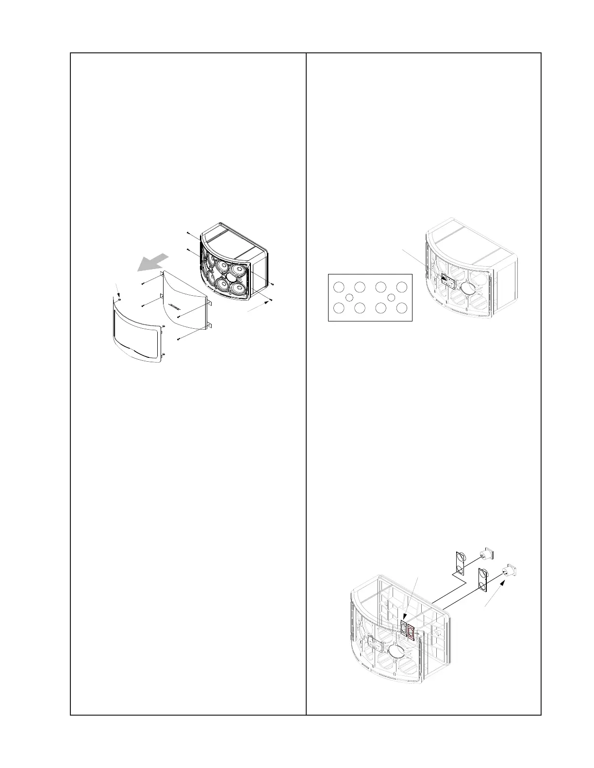
1. Grille Removal
1.1 Remove the four screws (16) securing
the trim ring (8) to the cabinet. Pull off the trim
ring leaving the four clips (17) in place on the
cabinet.
1.2 Remove the four screws (10) securing the
grille (6) to the cabinet. Pull off the grille.
2. Grille Replacement
2.1 Line up the grille (6) with the cabinet and
secure it with four screws (10).
2.2 Line up the trim ring (8) with the cabinet.
Press the trim ring into the four clips (17)
located in the corners of the cabinet.
2.3 Replace the four screws (16) securing the
trim ring to the cabinet.
3. Driver Removal
3.1 Perform procedure 1.
3.2 Remove the three screws (10) securing
the driver (1) to the cabinet. Lift out the driver.
3.3 Cut the wires as close as possible to the
driver’s wire terminal.
4. Driver Replacement
4.1 Referring to figures 1, 2, and 3, attach the
wires to the driver’s (1) wire terminal.
Tinnerman clips
located inside
on back wall
Speakon
connector
Shading network PCB
located inside
front wall
4.2 Line up the driver and gasket (2) to the
cabinet and secure it with three screws (10).
5. Shading Network PCB Removal/Access
5.1 Remove the position 2, 3, 6, and 7 drivers
(1) from the cabinet using procedure 3.1-3.2.
5.2 Using a short flat-blade screwdriver,
remove the two screws securing the shading
network PCB (3) to the inside wall of the
cabinet. Remove wires as needed.
6. Shading Network PCB Replacement
6.1 Referring to figure 2, replace any wires
that were removed.
6.2 Replace the two screws securing the
shading network PCB (3)
7. Speakon Connector Removal
7.1 Perform procedure 3.1-3.2 to remove the
position 2, 3, 6, and 7 drivers.
7.2 Using a flat-blade screwdriver, pry out the
tinnerman clip (5) securing the Speakon
connector (4) to the cabinet.
7.3 Pull out the Speakon connector and
remove the wires.
4
32
1
8
7
6
5
Top of speaker
Driver location
DISASSEMBLY/ASSEMBLY PROCEDURES
 Loading...