5
TEST PROCEDURES
3. Woofer Rub and Tick Test
3.1 Perform Disassembly/Assembly
procedure 5. Do not cut the wires at the
woofer assembly terminals.
3.2 Connect a signal generator directly to
the terminals of the woofer assembly
under test.
3.3 Apply a 10 Hz, 10 Vrms signal to the
woofer assembly.
3.4 Listen carefully for any extraneous
noises such as rubbing, scraping, or
ticking.
Note: To distinguish between normal
suspension noise and rubs or ticks,
displace the cone slightly with your fingers.
If the noise stays the same, it is normal
suspension noise and the woofer is fine.
Suspension noise will not be heard with
program material.
4. System Sweep Test
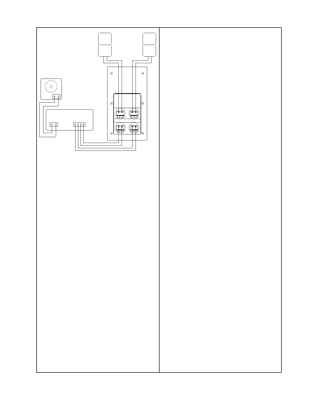
4.1 Set up the system as shown in
Figure 1.
4.2 Apply a 10 Hz, 10 Vrms sine wave to
the left and right signal inputs.
4.3 While listening to the output of the
system, sweep the input frequency slowly
up from 10 Hz to 500 Hz.
4.4 The output should smoothly cross over
from the bass module to the satellite
speakers.
4.5 Reduce the input voltage level to
5 Vrms.
4.6 Continue sweeping from 500 Hz to 15
kHz. Replace any satellite assembly that
buzzes or sounds distorted.
Note: The Acoustimass 5 Series III satellite
assemblies are non-repairable. If you have
a defective satellite assembly, it must be
replaced.
Inputs Outputs
Power Amplifier
+-+-
Audio Signal
Generator
Satellite Speakers
Acoustimass
Module
Figure 1. Acoustimass
®
5 Series III Test
Setup Diagram
1. Bass Module Air Leak Test
1.1 Apply a 100 Hz, 10 Vrms sine wave to
the left and right channel inputs of the bass
module. Do not connect the satellite
speakers.
1.2 Listen carefully for air leaks from
around the terminal cup and cabinet
seams. Air leaks will be heard as a hissing
or sputtering sound. All repairs must be
hidden. Test duration should be 5 seconds
minimum.
2. Woofer Phase Test
2.1 Apply a 50 Hz, 10 Vrms sine wave to
the left and right channel inputs of the bass
module.
2.2 While the signal is being applied to the
bass module, remove the input to one of
the channels.
2.3 The sound output level should drop by
approximately half. If the sound output level
increases or stays the same, then there is a
wiring problem in the woofers.
 Loading...