Installers Guide to the Bose® Serial interface June 28, 2011
Bose Confidential Information Page 8/42 Do Not Redistribute
3 The Physical Connector
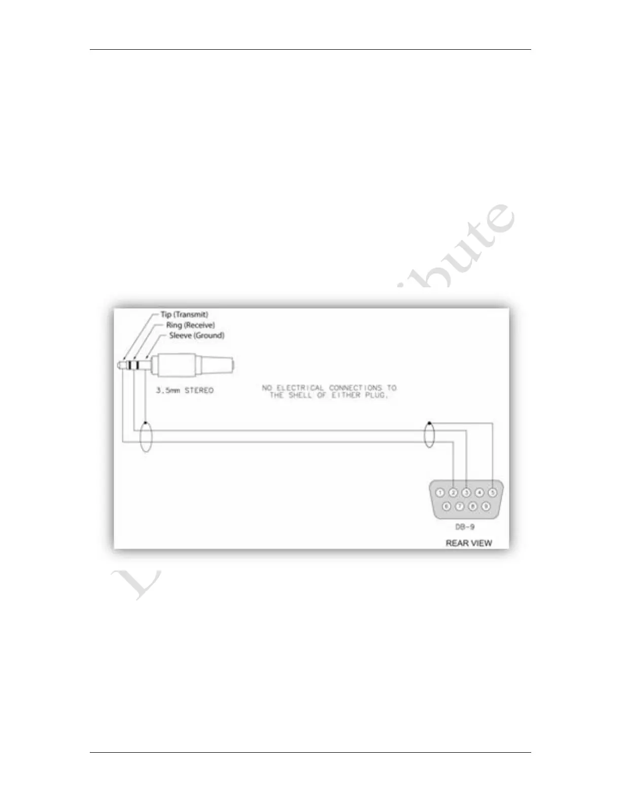
The interface is a 3.5mm stereo connector located on the rear of the Console at the same height
as the power connector. The cable that connects the computer (for example a PC) to the Console
connects the receive, transmit, and ground wires of a DB-9 connector to the tip, ring, and ground
connections of the Console connector.
The DB-9 male connector (e.g. on a PC) has pins labeled 1-5 in the top row and 6-9 in the bottom
row. Pin 2 (Receive) goes to tip, Pin 3 (Transmit) goes to Ring, and pin 5 (Ground) connects to
sleeve. See cable figure 1 below.
The physical signaling uses the standard RS232 serial communication electrical specifications
with communication parameters of: 19200 Bits per second, 8 Data bits, No parity, 1 Stop bit, and
No Flow control. Note that the Console voltage is zero when the communications link is not
actively transmitting a packet.
Figure 1 The Serial Connection Cable