24
Theory of Operation
7.0 Additional Electronics in the Console
7.1 Vacuum Fluorescent Display
A VFD module is installed in the front of the console. The module contains a microcontroller with
masked font tables, as well as built-in switching power supply/inverter and driver IC’s for control-
ling the VFD glass. Communication to the VFD is serial through J103; see sheet 2 of SD254135.
The protocol requires both clock (VFD_CLOCK) and data (VFD-DATA) lines, is single-direction
only, and runs at about 4800 baud. Q101 and Q106 are used to power-down the higher-current
sections of the VFD after the console has been off for about 10 seconds (reducing power con-
sumption and ensuring that the VFD is held in a reset state when the console is off).
7.2 DVD-ROM Drive
The DVD-ROM drive is a Toshiba SD-M1502 (soon to change to a SD-M1612). The drive is ca-
pable of playing DVD-video discs (including CSS decoding), CD-ROMs, and audio CDs. An ATAPI
cable for data and separate power cable connect the drive to the Main PCB (see sheet 2 of
SD254135). Q103 is used to reset the drive’s built-in microcontroller upon console power-up. The
drive remains active (in a paused state) for about 5 minutes after playing a CD/DVD to allow a
customer to return resume playback from the same location on the disc; after that, the drive is put
into a low-current standby mode via software command.
7.3 Console Keypad
A nine-button keypad is located next to the DVD-ROM drive tray. Six signals connect U1 to the
keypad: three signals represent the keypad rows, and three signals represent the keypad col-
umns. U1 identifies button presses by sequentially driving the KEYOUT lines (which activate
individual rows of keys) and reading-back the KEYIN lines (which have 75K pullup resistors inside
U1). If a button is pressed, the KEYIN line connected to that column of keys will be high (3.3V).
See SD256140.
7.4 Headphone Driver
The Headphone PCB holds the headphone jack itself, J200, and two inductors used to reduce
emissions and limit incoming ESD transients (L2001 and L2001). Pin 6 of the headphone jack is
used to sense when headphones are plugged in: when a customer inserts a headphone plug into
J200, pin 6 becomes shorted to ground. This pulls the HP-SENS line (normally pulled high by
resistor R242 on the Main PCB) to ground, alerting U1. U1 then mutes the appropriate audio
outputs. The headphone audio drive amplifier, U205, resides on the Main Board. This amp is config-
ured as a voltage follower (providing no signal gain).
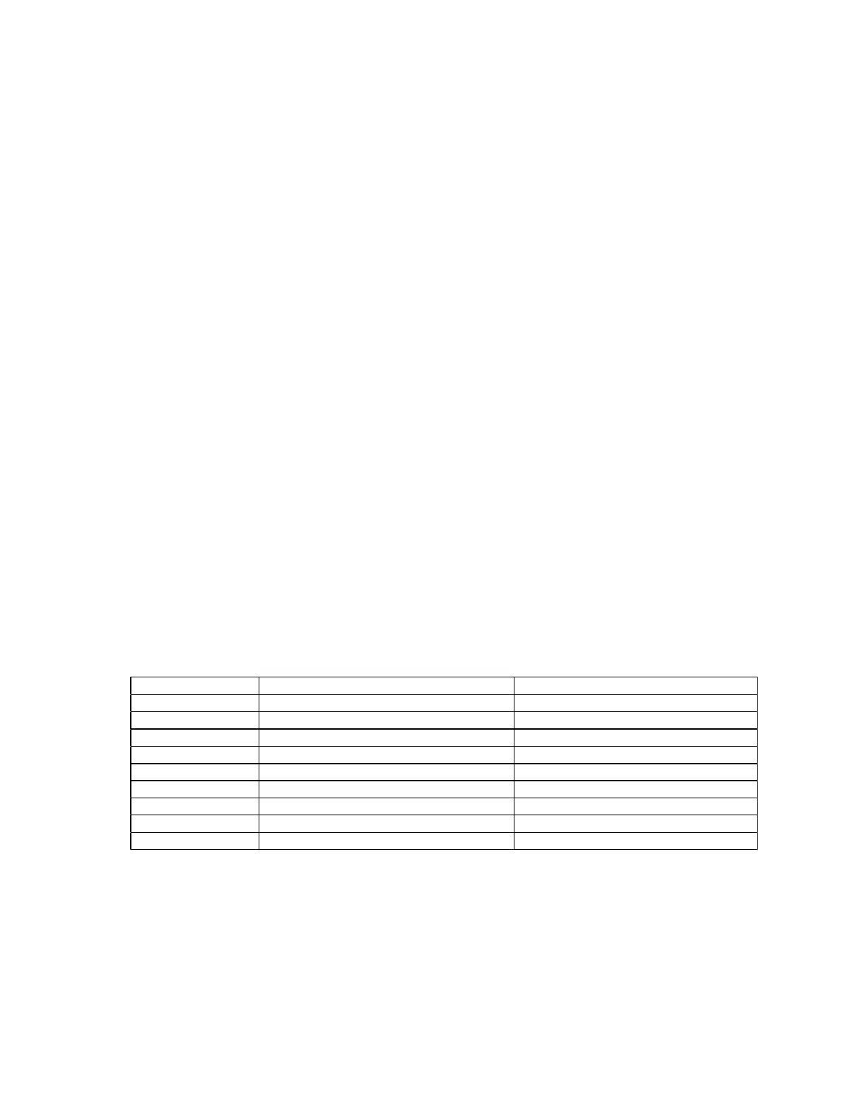
Console Button Row Column
ON/OFF Top (driven by KEYOUT2, J102-3) Left (read by KEYIN2, J101-6)
SOURCE Top (driven by KEYOUT2, J102-3) Center (read by KEYIN1, J101-5)
VOLUME UP Top (driven by KEYOUT2, J102-3) Right (read by KEYIN0, J101-4)
ALL OFF Center (driven by KEYOUT1, J101-2) Left (read by KEYIN2, J101-6)
ENTER Center (driven by KEYOUT1, J101-2) Center (read by KEYIN1, J101-5)
VOLUME DOWN Center (driven by KEYOUT1, J101-2) Right (read by KEYIN0, J101-4)
OPEN/CLOSE Bottom (driven by KEYOUT0, J101-1) Left (read by KEYIN2, J101-6)
ERASE Bottom (driven by KEYOUT0, J101-1) Center (read by KEYIN1, J101-5)
STORE Bottom (driven by KEYOUT0, J101-1) Right (read by KEYIN0, J101-4)