8
Theory of Operation
2.3 Supply Synchronization Generator
To limit radiated noise, all three switching supplies (12V, 5V and 3.3V) are synchronized to the
same control frequency. This frequency is varied by U1, as needed, to keep noise out of the AM
tuner.
U805 is a 74HC592 8-bit binary counter IC with an input register. An 11.2896 MHz clock signal is
fed to the counter clock (CCK) pin, and the chip counts on positive edges of this signal. Inputs A
through H are loaded to the register on positive edges of the register clock (RCK) signal, and the
register outputs are loaded to the counter when the active-low counter load (/CLOAD) is asserted.
These two signals are driven by the chip’s own active-low ripple carryout (/RCO), which is also the
output to the level shifter circuit. The active-low counter clock enable (/CCKEN) is pulled low by a
100 Ohm resistor, and the active-low asynchronous counter clear (/CCLR) is tied to the Main
PCB’s hardware reset line. The /RCO output is fed to a level shifter circuit (Q801 and Q804).
The synchronization clock is fed to all three switching power supply regulators in the console. The
clock frequency will be either 98.1704 kHz or 101.7081 kHz, depending on the state of
SUPPLY_FREQ_SEL, driven by U1. U1 picks the state based on AM tuner frequency.
2.4 Power Fail Detection
Q802 and Q803 detect a power failure by asserting the active-low /POWER_FAIL signal when the
console input voltage V_RAW falls below a given threshold (equivalent to an AC line voltage of
about 75 VACRMS). This signal is fed to U1 as an interrupt so the micro can perform some shut-
down functions before it is held in reset; see section 3.1.2 for additional information.
2.5 Grounding
R321 on the Tuner PCB connects PGND (the ground provided to the product by the power pack)
and GND (tuner signal ground). The power supply ground on the Main PCB is connected to GND
only at C832 and C828.
Additional signal ground connections between the Main and Tuner PCBs and between the PCBs
and the conductive paint on the plastics are made by conductive gasket material attached to the
plastic cover and base.
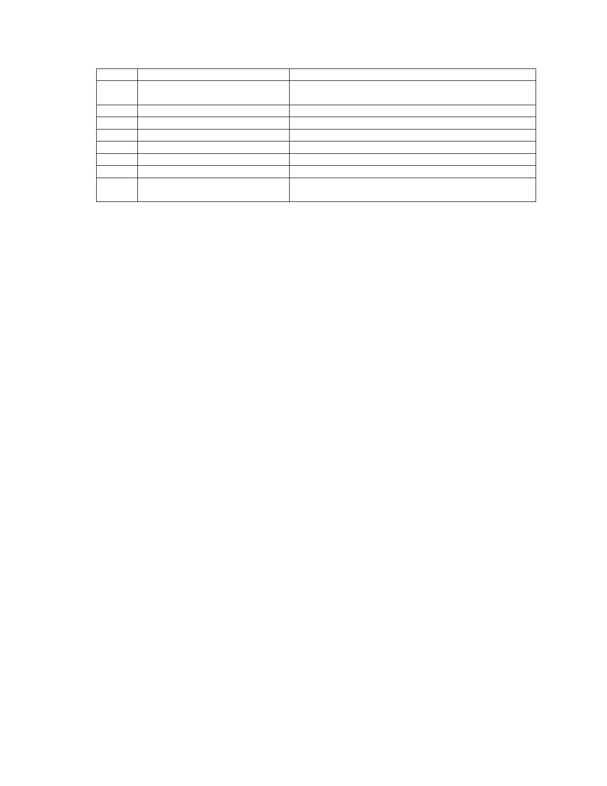
IC Pin Components Connected Pin Function
1 R301, C302, C303 Sets switching frequency (when not controlled
externally)
10 C308 Drives internal D-MOS
11 R322 Inhibits supply
12 R302, C305, C307 Lead-lag filter for compensation loop
13 R304, R305 Voltage feedback for control
18 C304 +5.1V for external reference
19 C306 Sets supply soft-start time constant
20 None Supply frequency switching synchronization
(see note)