78
15.3 Connect a 4 Ohm, 250 Watt load resis-
tor to the SMPS/Amplifier PCB’s J5 (Woofer)
connector. Connect the signal measurement
lead across the 4 ohm load and through the
Switching Amplifier filter to the meter.
15.4 Apply a 20Hz, -25dBu signal to the Input
2 1/4” TRS balanced input jack. Ensure the
output gain and THD+N levels are in accor-
dance with the Woofer output test table at
right.
16. Hall Effect Sensor Test
IMPORTANT NOTE: Reconnect the wiring
harness to J3 on the I/O - DSP PCB before
beginning these tests. This will connect the
output of the I/O - DSP PCB to the SMPS/
Amplifier PCB.
Re-connect the loudspeaker wiring harnesses
to J4 and J5 on the SMPS / Amplifier PCB to
enable output to the drivers.
CAUTION: You MUST disconnect the AC line cord from the unit when connecting the
driver wiring harnesses to the amplifier PCB outputs at J4 and J5 below. The smaller heatsink
plate on the amplifier PCB has high voltage (400V) on it when the unit is connected to AC mains.
The F1 Model 812 Loudspeaker changes its high frequency response when the Twiddler
®
array
is moved from the Straight position to the Reverse J, J, or C array patterns. Moving the Twiddler
array to one of these positions is sensed by the Hall Effect sensors located at each end of the
speaker enclosure. The DSP changes the EQ curve based on input from these sensors. Refer
to page 7 of this manual for a description of the various Twiddler array positions.
16.1 Set the Twiddler array to the Straight array pattern.
16.2 Set the Input 2 volume control to 12 o’clock (mid-point). Set the Input 1 volume control to
Minimum (fully CCW).
16.3 Apply a 100mv, pink noise signal to the Input 2 Left and Right RCA input jacks. Listen to the
loudspeaker output. You can download a pink noise .mp3 file from the F1 Loudspeaker product
page on the Bose Service web site at http://intranet.bose.com/tsg or http://serviceops.bose.com.
16.4 Move the Twiddler array to the Reverse J position. Verify that you can hear a difference in
the pink noise response. It should be noticeable in a relatively quiet environment.
16.5 Move the Twiddler array to the J position. Verify that you can hear a difference in the pink
noise response.
16.6 Move the Twiddler array to the C position. Verify that you can hear a difference in the pink
noise response.
TEST PROCEDURES
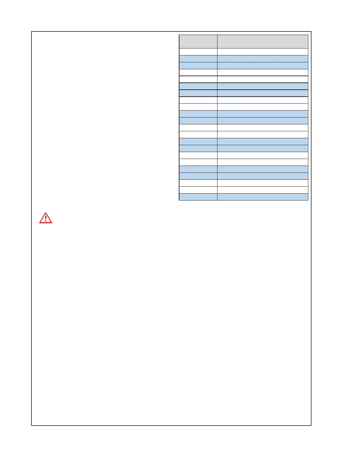
Input
Frequency
Output Level at J5
(Woofer Output)
20 Hz Bass Out < 5 dBu
30 Hz Bass Out = 10.4dBu +/-1dB
30 Hz THD+N < 1.0%
40 Hz Bass Out = 19.5dBu +/-1dB
40 Hz THD+N < 0.5%
50 Hz Bass Out = 24.8dBu +/-1dB
50 Hz THD+N < 0.5%
70 Hz Bass Out = 27.0dBu +/-1dB
70 Hz THD+N < 0.5%
100 Hz Bass Out = 22.7dBu +/-1dB
100 Hz THD+N < 0.5%
200 Hz Bass Out = 18.5dBu +/-1dB
200 Hz THD+N < 0.5%
400 Hz Bass Out = 8.8dBu +/-1dB
400 Hz THD+N < 1.0%
580 Hz Bass Out = 7.0dBu +/-1dB
580 Hz THD+N < 2.0%
740 Hz Bass Out = 9.2dBu +/-1dB
740 Hz THD+N < 2.0%
1 KHz Bass Out = 5.2dBu +/-1dB
1 KHz THD+N < 2.0%
2 KHz Bass Out < 5 dBu

 Loading...