79
TEST PROCEDURES
17. Air Leak Test
17.1 Set the Input 1 MIC/LINE switch to LINE. Set the Input 1 volume control to Maximum.
17.2 Apply a balanced 48Hz, 55 mVrms sine wave to the Input 1 XLR connector.
17.3 Sweep the input frequency from 48Hz to 60Hz. Listen for air leaks around the cabinet
gaskets. Replace any defective gaskets. Note: Not all gaskets are stocked as repair parts.
17.4 Listen for any rubbing or ticking of drivers. Replace any defective drivers.
18. Power Sweep Test
18.1 Set the Input 1 MIC/LINE switch to LINE. Set the Input 1 volume control to Maximum.
18.2 Apply a balanced 1kHz, 45 mVrms sine wave to Input 1 XLR connector.
18.3 Sweep the input frequency from 20Hz to 5kHz. Sweep time should be 4 seconds up and
4 seconds down. Listen carefully for buzzes, rattles, or other extraneous noises from the drivers
or from the internal parts. Note: The whooshing noise from the port from 40 to 50 Hz is accept-
able. Replace any driver that has a buzzing noise, or is defective.
IMPORTANT NOTE: After completion of these test procedures, perform the Hi-Pot and Ground
Bond tests, which are located on page 85 of this manual. These tests are mandatory and must
be completed before returning the product to the customer.
F1 Subwoofer Tests
Equipment Required:
• Balanced audio signal generator
• Balanced input audio signal
analyzer / dB meter
• Switching Amplifier filter,
AP AUX-0025 or equivalent
• Balanced XLR male cable
• Balanced XLR female cable
• AC line cord
• 2 - 4 ohm, 250 Watt load resistors
1. Power-up Test
1.1 Connect the unit under test to AC
mains.
1.2 Turn on the AC power switch. Verify that there is no loud turn-on pop. Verify that the Power/
Fault LED is lit BLUE. If it is RED, there is a failure and the unit will need to be troubleshot and
repaired.
1.3 Place the Front LED switch to the POWER position. Verify that the front LED located at the
lower right front of the speaker is lit blue.
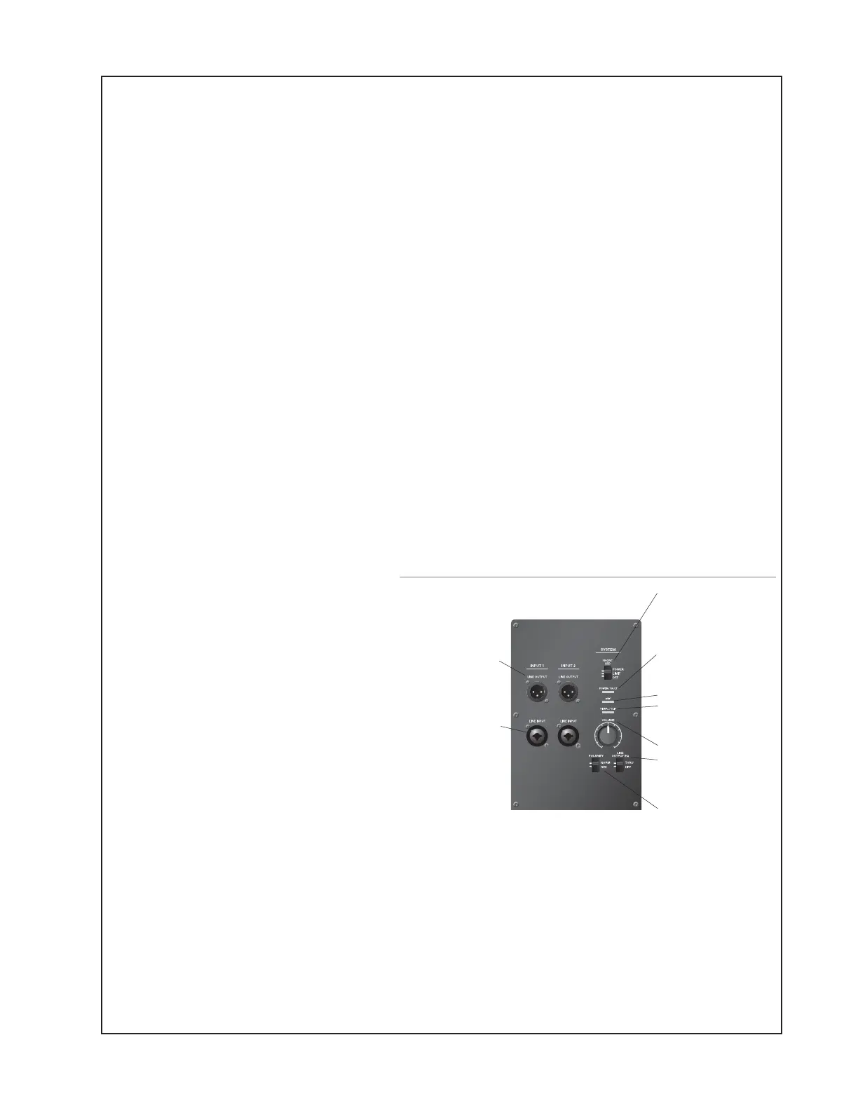
F1 Subwoofer Control Panel
FRONT LED
: selector switch:
• POWER enables LED to indicate
power status.
• LIMIT enables LED to indicate
limiting.
• OFF turns o LED.
POWER/FAULT :
indicates power/fault
status
• Blue = power on.
• Red = fault condition.
LIMIT:
Red = system limiting.
SIGNAL/CLIP:
Displays the input
signal status in color.
• Green = signal present.
• Red = signal clipping.
VOLUME
– Adjusts subwoofer volume.
LINE OUTPUT EQ:
• THRU passes input signal to the
output with no filtering.
• HPF passes input through a
high-pass filter.
POLARITY:
• NORM allows normal operation.
• REV causes bass phase cancellation
when the F1 Model 812 loudspeaker
is mounted on the supplied stand.
May be used to better align the
bass when the subwoofer is located
further away from the F1 Model 812
loudspeaker.
LINE OUTPUT 1 & 2:
Individual
outputs that provide balanced line
output signals (pre-fader) that can
be sent to powered loudspeakers
or additional subwoofers.
Note : When the LINE OUTPUT EQ
selector switch is set to THRU, the
LINE OUTPUT signal will be full
range.
LINE INPUT 1 & 2:
Combination
XLR – ¼" phone connector inputs
that accept line level signals.

 Loading...