81
TEST PROCEDURES
3.8 Measure the output level at the Input 1 Line Output connector. It should be equal to the input
signal level, +/- 1 dB.
4. Maximum Input Voltage Test
4.1 Apply a balanced 1 kHz, +24 dBu signal to the Input 1 XLR connector.
4.2 Measure the THD+N level at the Input 1 Line Output connector. It should be < 0.01%.
5. Input 1 Frequency Response Through Pre-amp
5.1 Ensure that the Line Output EQ switch on the input panel is in the THRU position.
5.2 Apply a balanced 20 Hz, 0 dBu signal to the Input 1 XLR connector.
5.3 Measure the output level at the Input 1 Line Output connector. It should be 0 dBu, +/- 0.5 dB.
5.4 While measuring the output level, slowly increase the input frequency from 20 Hz to 20 kHz.
The output level should be 0 dBu, +/- 0.5 dB.
6. Input 1 High Pass Frequency
Response Test
6.1 Move the Line Output EQ switch to the
HPF position.
6.2 Apply a balanced 20 kHz, +20 dBu
signal to the Input 1 XLR connector.
6.3 Measure the output level at the Input 1
Line Output connector. It should be +20
dBu, +/- 1 dB.
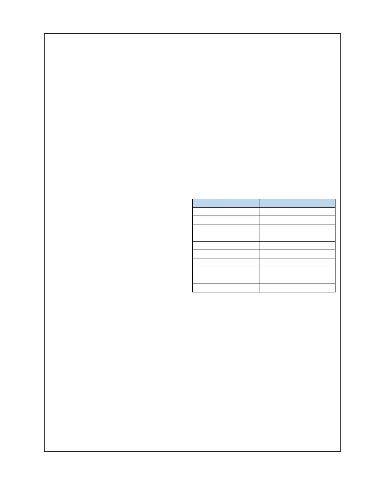
6.4 Change the input frequency in accordance with the table above right. Verify that the output
level at the Input 1 Line Output connector is as listed, +/- 1 dB.
6.5 Repeat tests 2 through 6 for the Input 2 XLR connector. Outputs are measured at the Input
2 Line Output jack.
SMPS / Amplifier PCB Tests
The following tests will test the I/O - DSP PCB and the SMPS / Amplifier PCB together as a
unit, disconnected from the woofers. The I/O - DSP PCB itself was tested in the previous test
series.
• Remove the six screws that secure the I/O - DSP PCB to the enclosure. Re-connect the
10-pin wiring harness to connector J3. This will re-connect the I/O - DSP PCB to the SMPS /
Amplifier PCB assembly. Ensure all other wiring harnesses are connected. Re-install the
I/O - DSP PCB into the loudspeaker enclosure.
Frequency Input
Output Level
Freq = 20KHz
20 dBu +/-1dB
Freq = 10KHz
20 dBu +/-1dB
Freq = 5KHz
20 dBu +/-1dB
Freq = 1KHz
20 dBu +/-1dB
Freq = 500 Hz
20 dBu +/-1dB
Freq = 200 Hz
19 dBu +/-1dB
Freq = 100 Hz
11 dBu +/-1dB
Freq = 70 Hz
1.5 dBu +/-1dB
Freq = 50 Hz
-9.5 dBu +/-1dB
Freq = 30 Hz
-27 dBu +/-1dB
 Loading...