16
DISASSEMBLY PROCEDURES
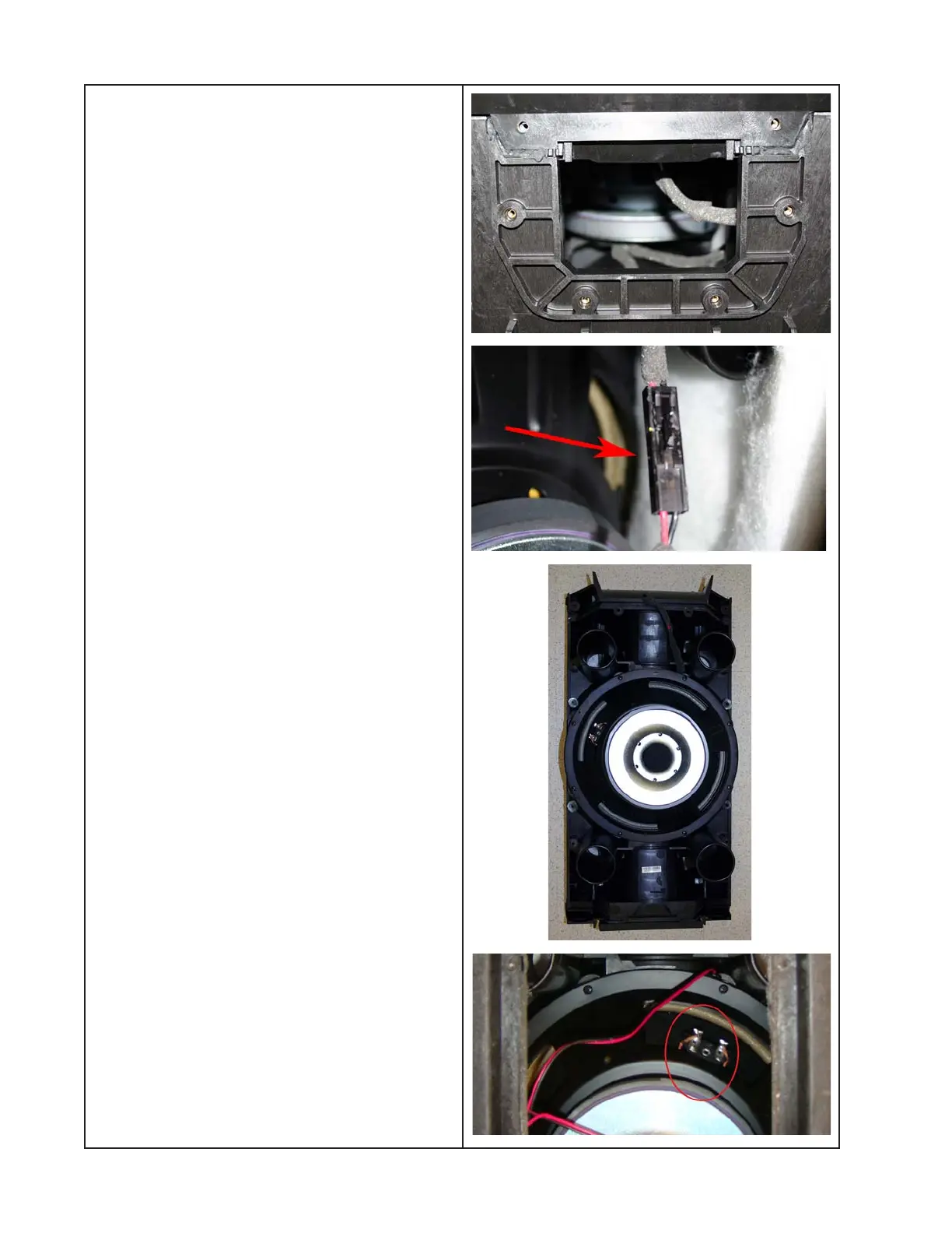
7.3 Place the loudspeaker onto its back.
Remove the stand mount interface using
procedure 6.
7.4 Once the screws are removed, you are
ready to separate the woofer baffle from the
loudspeaker enclosure.
Separate the front section of the enclosure
from the rear section by pulling them apart at
the opening left by the removal of the stand
mount interface. Refer to the photo at right.
Lift off the front enclosure section. Once the
front section has come loose, you can rest
the ports on the internal brackets to allow
disconnecting the wiring harnesses.
Note: Take care to not damage the large
main enclosure gasket. You will need to re-
use it. If you do damage it, you can order a
replacement.
7.5 Disconnect the two Faston connectors
from the woofer. Disconnect the Twiddler
array connector, which is in-line with the
wiring harness from the crossover PCB to
the Twiddler array (see photos at right). Lift
off the front enclosure section.
7.6 Place the front enclosure section face
down on the bench. Remove the eight
screws that secure the woofer to the woofer
baffle. Lift off the woofer.
Re-assembly Notes:
- Make sure the woofer terminals face the
same way as the removed woofer, near the
port, to allow terminal access when re-
connecting the wiring harness. See photo
bottom right.
- Be sure to correctly place the main enclo-
sure gasket in the groove along the edge of
the enclosure to ensure there are no air
leaks after the woofer baffle is replaced.
- After woofer baffle replacement, ensure that
there are no air leaks using the test proce-
dures in this service manual.