17
DISASSEMBLY PROCEDURES
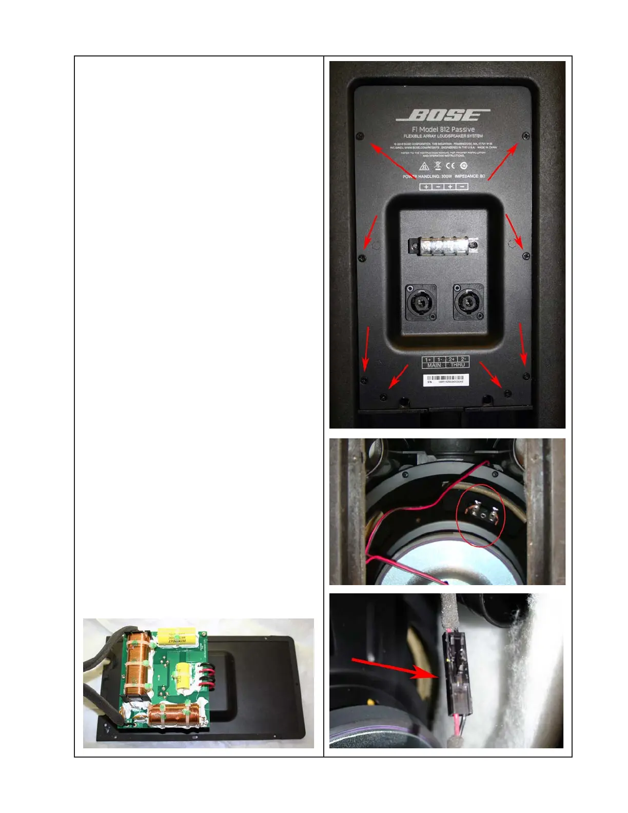
8. Input Panel / Crossover PCB Assembly
Removal
8.1 Remove the six screws that secure the
Crossover PCB assembly to the loud-
speaker enclosure.
Re-assembly Note: The two longer screws
should be reinstalled in the bottom two holes.
8.2 Carefully lift the Crossover PCB assem-
bly away from the enclosure. Take care to
not damage the gasket.
Note: The crossover PCB assembly in-
cludes the rear panel sheetmetal and the
wiring harnesses. See photo below.
Note: The blank panel on the back of the unit
below the input panel has no components
behind it. There is no need to remove this
panel for repair.
8.3 Disconnect the two Faston connectors
from the woofer (see photo at right).
Re-assembly Note: Be sure to observe
polarity when re-connecting the woofer
harness.
8.4 Disconnect the Twiddler array connector,
which is in-line with the wiring harness from
the crossover PCB to the Twiddler array
(see photo at bottom right).