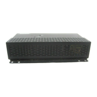
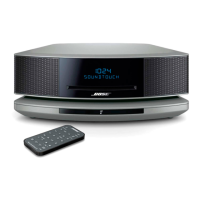
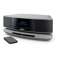
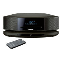
4. Twiddler Power Output Test
NOTE: This test can be performed with a fully
assembled module. Refer to the second note in
Procedure 3 before making any connections.
A. Connect an 8Ω resistive load and a voltmeter
across either the left or right twiddler output
terminals.
NOTE: These measurements can be obtained at
120 and 240 V. Results will vary depending on
the line voltage used.
B. Connect an oscillator to the module’s L/R
audio input terminals. Adjust the oscillator to 1
kHz, 465 mVrms.
C. Measure the voltage across the load. It should
be approximately 20 volts (50 watts).The signal
should look undistorted when viewed on an
oscilloscope.
5. Twiddler Short Circuit Protection Test
NOTES: This test can be performed with a fully
assembled module. Refer to the second note in
Procedure 3 before making any connections.
A. Adjust the oscillator to 400 Hz, 180 mVrms.
Connect an 8Ω resistive load and a voltmeter
across either the left or right twiddler output
terminals. The output voltage should measure
approximately 8 Vrms. Momentarily short the left
or right twiddler output terminals. The signal
should mute for approximately 2-3 seconds.
6. Compressor Test
NOTE: This test can be performed with a fully
assembled module. Refer to the second note in
Procedure 3 before making any connections.
A. Connect an oscillator to the module's L/R
audio input terminals. Adjust the oscillator to 1
kHz,1.1 Vrms.
B. Connect an 8Ω resistive load across either the
left or right twiddler output terminals.
20
3. Frequency Response of L/R (Twiddler) Channels
NOTE: This test can be performed with a fully
assembled module.
A. Connect an oscillator to the module’s L/R
audio input terminals. Adjust the oscillator to 1
kHz,30 mVrms for a 0 dB reference.
NOTE: There are 2 sets of twiddler output
terminals for each channel. Refer to the I/O PCB
Schematic before attempting any connections.
For the left channel,connections should be made
to pins 8 (+) and 5 (-). For the right
channel,connections should be made to pins 4
(+) and 1 (-). This note applies to Procedures 3
through 6.
B.Connect an 8Ω resistive load across either the
left or right twiddler output terminals. Using a dB
meter,measure the response according to the
chart given below.
C. Repeat this test for the other channel.
Frequency Relative Response
100 Hz -17.6 dB ± 2.0 dB
210 Hz +1.3 dB ± 1.5 dB
320 Hz - 6.2 dB ± 1.8 dB
1 kHz 0 dB
1.8 kHz -6.5 dB ± 1.5 dB
10 kHz -2.0 dB ± 1.5 dB
36 kHz -5.3 dB ± 2.0 dB