21
DISASSEMBLY PROCEDURE
Important Notes!
*Place the system in “Ship Mode” prior to disas-
sembly by entering the TAP command “sh”.
See
TAP command set up on page 30.
Metal shavings might come out when removing
screws from the aluminum boss in the housing.
Effort must be taken to avoid metal shavings from
entering the unit. Use a vacuum to remove any
metal shavings.
1. Grille Removal
Note: The grille is held in place by Pressure Sensi-
tive Adhesive (PSA) strips located in the center of
the grille (fi gure 5.) and also by two tabs on either
end of the grille (fi gure 3).
To avoid destroying the grill during the removal
process, brush alcohol over the PSA strips (fi gure
5) before attempting to remove it.
Important Note: To avoid damage to the cabinet,
do not use the cabinet as a pry point to remove the
grille.
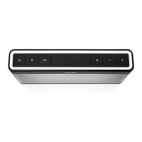
1.1 At the location shown in Figure 3, insert the tip
of a plastic tool, such as a spudger, between the
grille and its rubber gasket.
Note: The location shown is between the PSA and
grille tabs securing the grille.
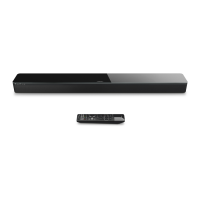
1.2 Rotate the spudger away from you while prying
against the rubber gasket. Figure 4.
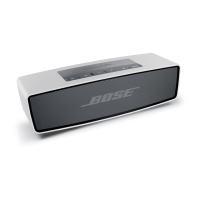
1.3 Once a portion of the grille is released, grasp
the grille and pull it across the unit lengthwise to
release the PSA. Figure 5.
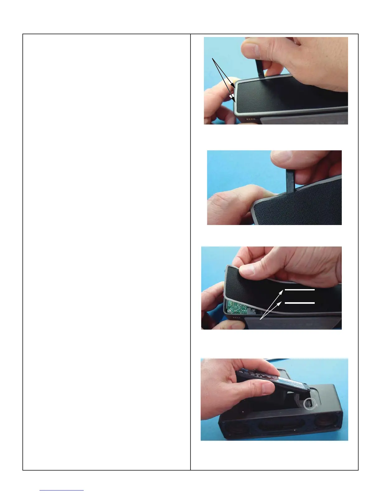
2. Battery Removal
The Battery in SoundLink
®
Mini II is hardwired to
the Boost PCB. See fi gure 6. Place the product in
ship mode prior to disassembly. See entering ship
mode on page 33.
The rear grille, I/O PCB, rear baffl e and Amp PCB
must be removed before the Battery and Boost
board can be removed. Use the following procedure
to remove the battery and the boost board in order
to unsolder the cable and replace the battery.
Figure 3.
Figure 4.
Figure 5.
Figure 6.
Grille TABs
PSA Strips
Battery cable is soldered
to the Boost PCB
 Loading...