22
DISASSEMBLY PROCEDURE
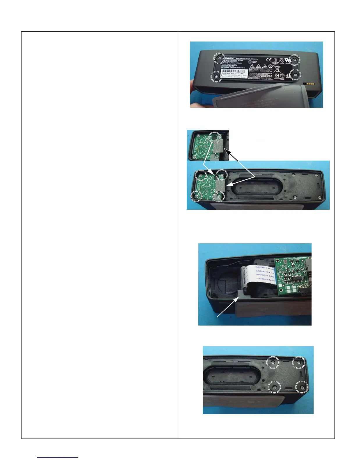
Battery removal Removal (Continued)
2.1 Remove the foot by pulling it away from the
battery.
2.2 Remove the four screws securing the battery to
the cabinet. Figure 7.
2.3 Remove the four screws securing the I/O PCB
to the cabinet as shown in Figure 8.
2.4 Carefully peel away the foam tape securing the
FFC cable to the I/O PCB connector. This foam will
be damaged when removing, plan to replace the
foam with part number 373978-0010, see item 8 on
page 7.
Note: When handling the I/O board, do not to touch
the microphone fi lter with fi ngers. Gloves should be
used to avoid contact with the fi lter. Figure 8.
The replacement I/O PCB does not include the
microphone fi lter. Install new part (744588-0010)
when replacing the I/O PCB.
2.4 Move the I/O PCB to the right until the AUX
connector clears the housing and then lift the top
edge of the PCB until the USB connector clears the
housing. Figure 9.
2.5 Partially lift out the I/O PCB. Lift up the connec-
tor locking tab to release the FFC cable from the
I/O PCB connector.
2.6 Pull the battery cover out of the retaining slot in
the cabinet. Figure 9.
2.7 Remove the four screws securing the rear baf-
fl e. Figure 10.
Figure 7.
Figure 8.
Figure 9.
Figure 10.
Microphone
Filter
Foam Tape
Battery Cover Tab
 Loading...