Do you have a question about the Boss TU-12 and is the answer not in the manual?
Step-by-step guide for replacing the 9V battery in the device.
Recommendation to remove the battery to prevent leakage during extended periods of non-use.
Information on indicator behavior and amplifier noise when using the AC adaptor.
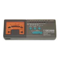
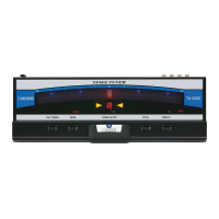
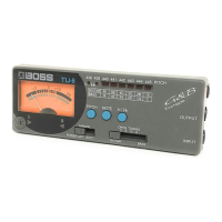
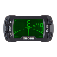
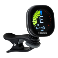
How to interpret indicator lights to check the produced tone.
Guide on how to select the desired pitch for tuning.
Process for selecting the specific string to be tuned on a guitar or bass.
Method for checking tone using the meter and tuning guide.
| Display | Needle meter |
|---|---|
| Reference Pitch | A4 = 440 Hz |
| Input | 1/4" Phone Jack |
| Accuracy | +/- 1 cent |
| Type | Chromatic Tuner |
| Output | 1/4" phone jack |
| Power Supply | 9V battery |
| Input Impedance | 1M ohm |
| Accessories | 9V Battery |