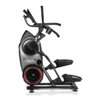
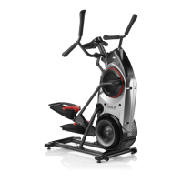
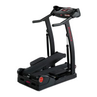
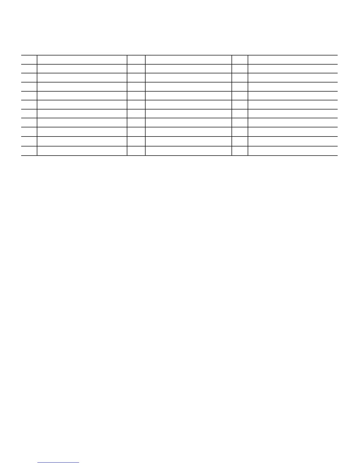
9
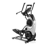
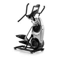
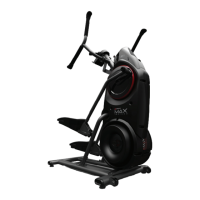
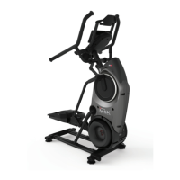
A Dynamic Handlebar, Left L Transport Wheel W Power Cord
B Console Assembly (w/Aerobars) M Stabilizer X Arm Drive Assembly
C Media Capture Bar N Leveler Y Crank Arm
D Dynamic Handlebar, Right O Pedal Z Drive Pulley, Lower
E Crank Cover P Foot Pad AA Fan Belt
F Shroud, Right Q Roller BB Disc Brake
G Cap R Leg CC Speed Sensor
H Shroud, Right Fan S Shroud, Left Fan DD Speed Sensor (behind Fan)
I Fan Assembly Inserts T Frame Assembly EE Tensioner
J Shroud, Rear U Upper Shroud FF Drive Belt
K Rail Assembly V Shroud, Left GG Drive Pulley, Upper