P
7A
P
7A
P
7A
P
7A
1
2
3
4
SW
5
6
7
12
N2
3
GB
INSTALLATION
INSTRUCTIONS
FLOOR
CODER/DECODER CD/204
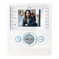
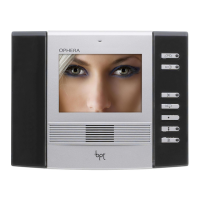
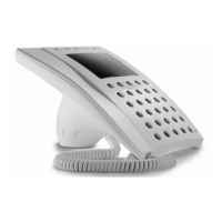
The unit enables the C/200 hand
set, the VM/200 - VM/203 serie
monitors and VMF/200 - VMF/20
monitors to be installed in code
call installations.
The CD/204 unit enables 4 rece
vers to be connected and is the
refore an excellent solution fo
encoding/decoding on the floor.
Only one receiver plus an RC/20
call repeater can be connected t
a CD/204 output.
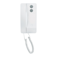
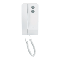
Owing to its small size, the un
can be inserted in a regular con
nector box (90 x 90 x 40 mm), o
can be installed on a DIN guid
(EN 50022) (fig. 3).
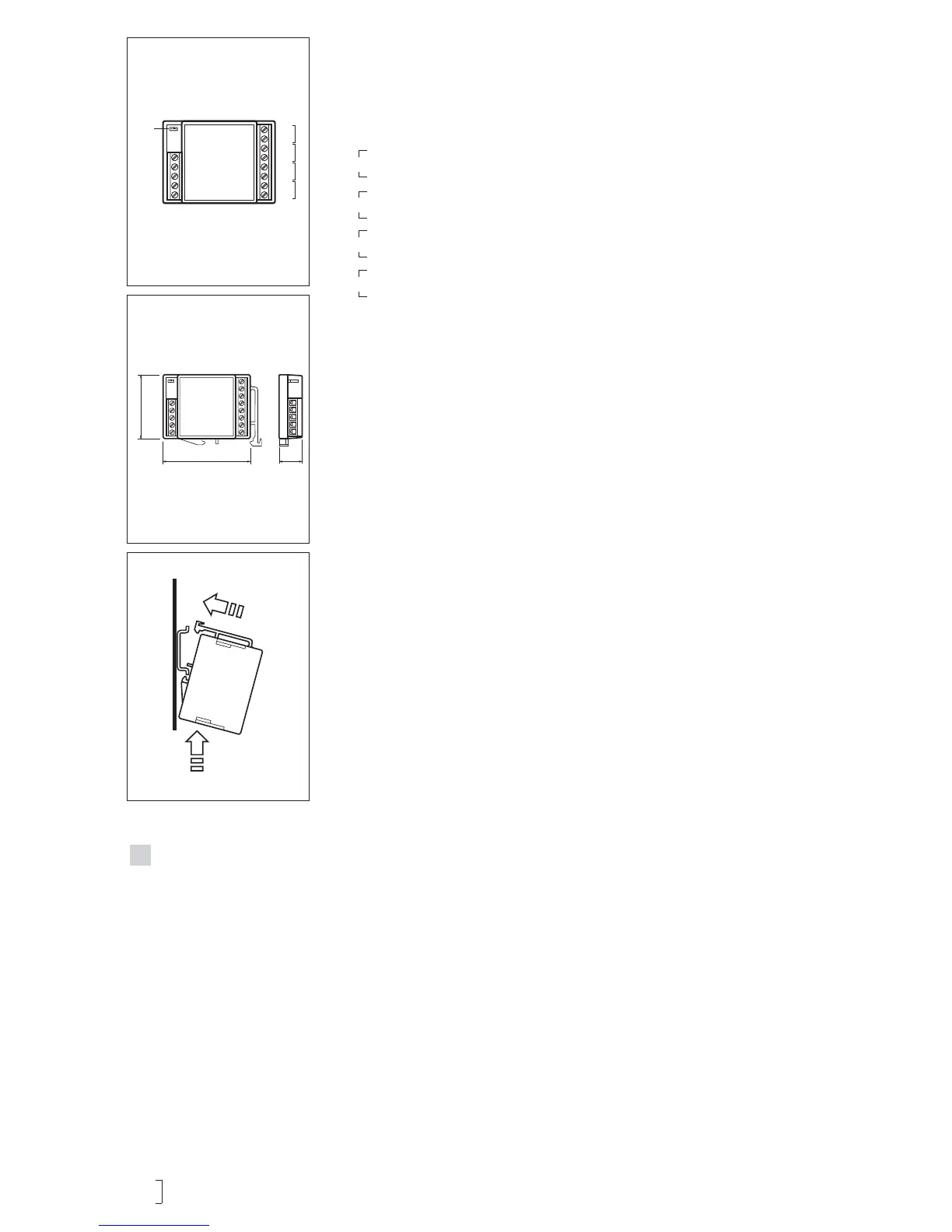
Function of each terminal (fig. 1)
Terminal block C-IN
5 − 10 ÷ 18V DC
6
7 coded call from entry panel
12 coded call to porter’s switch-
board
N2 enabling of second call note
Terminal block C-IN
P call to porter’s switchboard
from receiver 1
7A call to receiver 1
P call to porter’s switchboard
from receiver 2
7A call to receiver 2
P call to porter’s switchboard
from receiver 3
7A call to receiver 3
P call to porter’s switchboard
from receiver 4
7A call to receiver 4
Programming
Power up the unit and remove
he SW software programming
Send the code relating to the
ser connected to output 1 via the
oded call entry panel, or the
PD/100 porter’s switchboard.
f the programming jumper is
nserted at this point, the codes
ollowing the one transmitted are
ssigned to the other 3 users in
f, on the other hand, the installer
ishes to assign each user a non-
rogressive code, send the code
elating to the user connected to
utput 2, followed by the code
elating to the user connected to
utput 3, and lastly the code rela-
ing to the user connected to out-
Insert the SW jumper.
N.B. If the programming is carried
out via the porter’s switchboard,
the acknowledgement of the com-
pleted programming is given by the
code sent to the extension appea-
ring on the display (PORTER
CALL).
he unit generates two types of
all note:
a: continuous bi-tonal note lasting
t least one second;
b: rings lasting 0.6 seconds repea-
ed every 2 seconds, for the dura-
ion of the call, with a minimum of
he unit is factory set with the note
ype a for calls from the entry
anel, and with note type b for
alls from the porter’s switchboard
the connection must be made to
erminal N2 before note type b can
he type of note can be inverted
y sending the code 80160 (block
ode) or 13120 (progressive-
n order to reset the initial condi-
ions, send the code 80161 (block
ode) or 13121 (progressive-
he modification of the call note
ust be carried out when in pro-
ramming mode (with the SW
umper disconnected).
Technical features
Supply voltage: 10 ÷ 18 VDC.
Current demand: 8mA (110 mA
during call).
Maximum number of CD/204
units which can be connected
in a block: 200.
Working temperature range:
from 0°C to +35°C.
• Dimensions: 60 x 44 x 16 mm.