pulsante servizi ausiliari: max. 24 V, 1 A.
6
GB
INSTRUCTIONS FOR USE
AND INSTALLATION
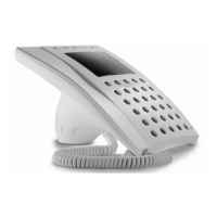
HANDSET YC/200
he unit has a door-lock release but-
on and features an electronic
all facility. It can accommodate the
uxiliary services button ( ) YP1
nd loudspeaker YAL to make the
Dimensions: 98x215x63 mm.
Note. In intercom systems, the door-
lock release button is enabled while
you are talking with the entry panel.
Door-lock release button
ormally the door-lock release button
s active. If you want it active only
hen the receiver is lifted, cut the
umper BP1 (fig.5).
Function of each terminal (fig. 5)
Terminal block C
5 ground
7 call
8 audio from entry panel
9 audio to entry panel
HANDSET YC/200A
eatures similar to handset YC/200, it
lso has a button for auxiliary servi-
- Maximum switching power of auxi-
liary services button: max. 24 V, 1 A.
Can accommodate 2 modules (YP3
and YPL).
HANDSET YC/201
Handset with secrecy of speech.
Features similar to receiver YC/200A.
Unit YP3 can be used to add 3 auxi-
liary buttons to the handset.
Door-lock release button
Normally the door-lock release button
is active after having received a call.
If you want it active only when the
receiver is lifted, after having recei-
ved a call, cut the jumper BP1 (fig. 6).
Function of each terminal (fig. 6)
Terminal block C
5 ground
7 call
8 audio from entry panel
9 audio to entry panel
20 landing call input
E audio enabling (
1
)
button for
auxiliary services
Terminal block C (accessories)
connection for
YAL loudspeaker
7A connection for
7 YPL module
(
1
) Connection required for special
installations (combined audio entry
and video entry systems).
Connecting YPL unit
When the YPL unit is installed in the
receiver, wire jumper BP2 must be
cut (fig. 6).
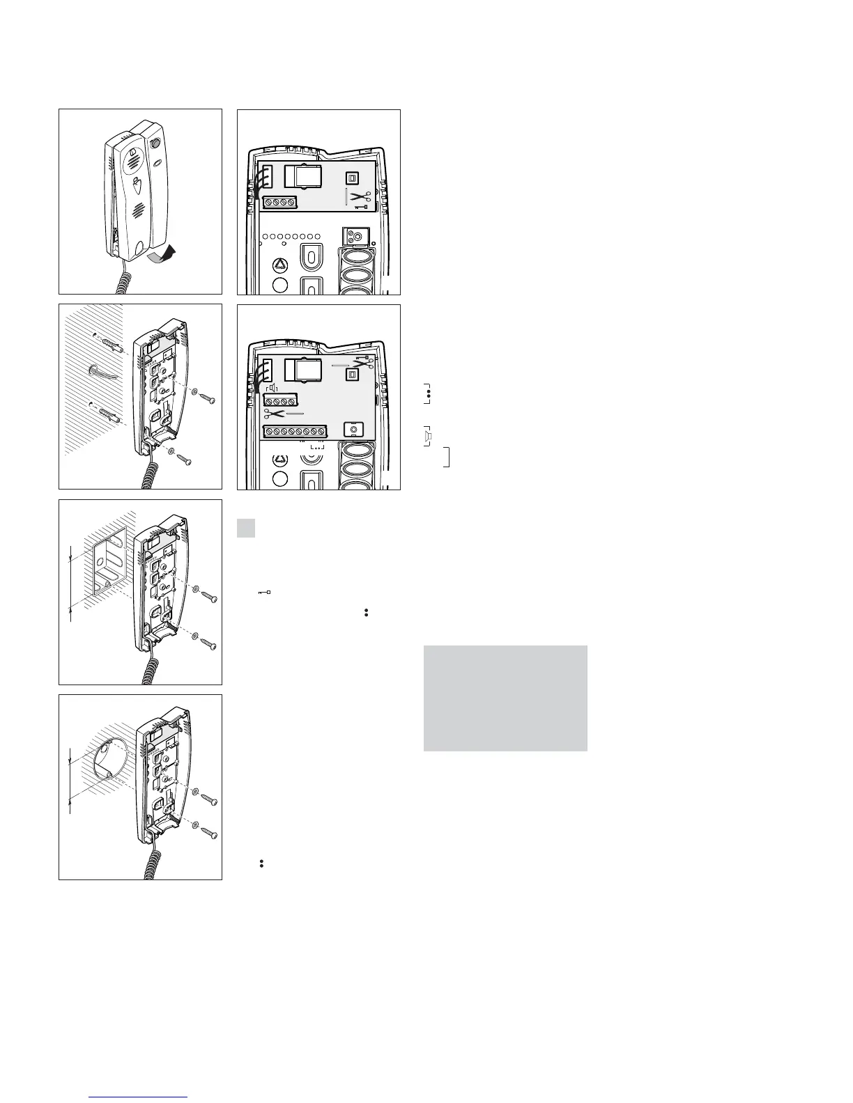
Installation
First, remove the housing (fig. 1) and
fasten the base directly to the wall
(fig. 2) or to the embedding box (fig.
3 or 4).
If walls are not perfectly level, do not
overtighten screws.
WARNING FOR THE USER
• Please do not open or tamper with
the device.
• The device operating with a very low
voltage (24 VAC - 50 VDC) and cannot
be connected to higher voltages.
• In the case of breakdown or modifi-
cation of the apparatus (such as power
supplier…) please contact a speciali-
zed maintenance service.