8
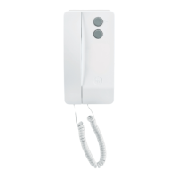
NC/220 HANDS-FREE
AUDIO MODULE
Hands-free audio module for use in
series 200 audio entry installations.
Is inserted in a standardised rec-
tangular single embedding box.
The unit comes with adapters for
the use of a number of commer-
cially available front plate models.
Hooks are applied on the back of
the module for the possible assem-
bly of the CD/200 decoder.
The operation of the hands-free-
module requires the GVV/200 main
control unit.
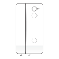
It features the following controls
(fig. 1):
•
Auxiliary services
•
Door-lock release
Audio (the button must be
kept pressed for the entire
duration of the conversation)
Function of each terminal (fig. 2)
5 power supply (common)
7 call
8 audio to receiver
9 audio to entry panel
•
aux
•
Function of jumper SW1
Normally supplied ready inserted.
Remove the jumper in the event the
volume of the call note is to be atte-
nuated (fig. 2).
Technical features
• Maximum switching power of the
auxiliary services button: max.
24V 50 mA.
• Working temperature range: from
0 °C to +35 °C.
NOTE. Handsets cannot be instal-
led together with NC/220 hands-free
modules in the same installation.
GB
INSTALLATION
INSTRUCTIONS
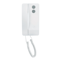
NC/221 HANDS-FREE
AUDIO MODULE
Amplified hands-free audio modu-
le, similar in design to mod.
NC/220, for use in series 200 audio
entry (with secrecy speech) and
video entry installations.
Is inserted in a standardised rec-
tangular single embedding box or
combined with the monitor module
in a standardised double embed-
ding box.
The operation of the hands-free
module requires the GVV/200 main
control unit.
Function of each terminal (fig. 3)
E enabling
5 power supply (common)
7 call
8 audio to receiver
9 audio to entry panel
20 door bell
•
aux
•
Function of jumper SW1
Normally supplied ready inserted.
Remove the jumper in the event the
volume of the call note is to be atte-
nuated (fig. 3).
Technical features
• Maximum switching power of the
auxiliary services button: 24V 50
mA.
• Working temperature range: from
0 °C to +35 °C.
NOTE. Receivers with handset and
NC/221 hands-free modules can
be installed in the same installation.
Installation of the modules
Recess the embedding box flush
with the wall at a suitable height for
the user.
Examples of assembly of the
hands-free module in a standardi-
sed single embedding box with a
number of commercially available
front plates (fig. 4):
1 (fig. 5)
A (embedding box).
B (BTICINO Living series art.
L4803 or Light series art. N4803
front plate, VIMAR Plana series
art. 14653 front plate).
2 (fig. 6)
A (embedding box).
B (adapter for VIMAR plate).
C (adapter for AVE plate).
D (BPT hole plug adapter).
E (VIMAR Idea or Rond series
front plate, AVE system 45 front
plate).
3 (fig. 7)
A (embedding box).
B (BPT hole plug adapter without
connecting rods).
C (GEWISS Playbus series front
plate).
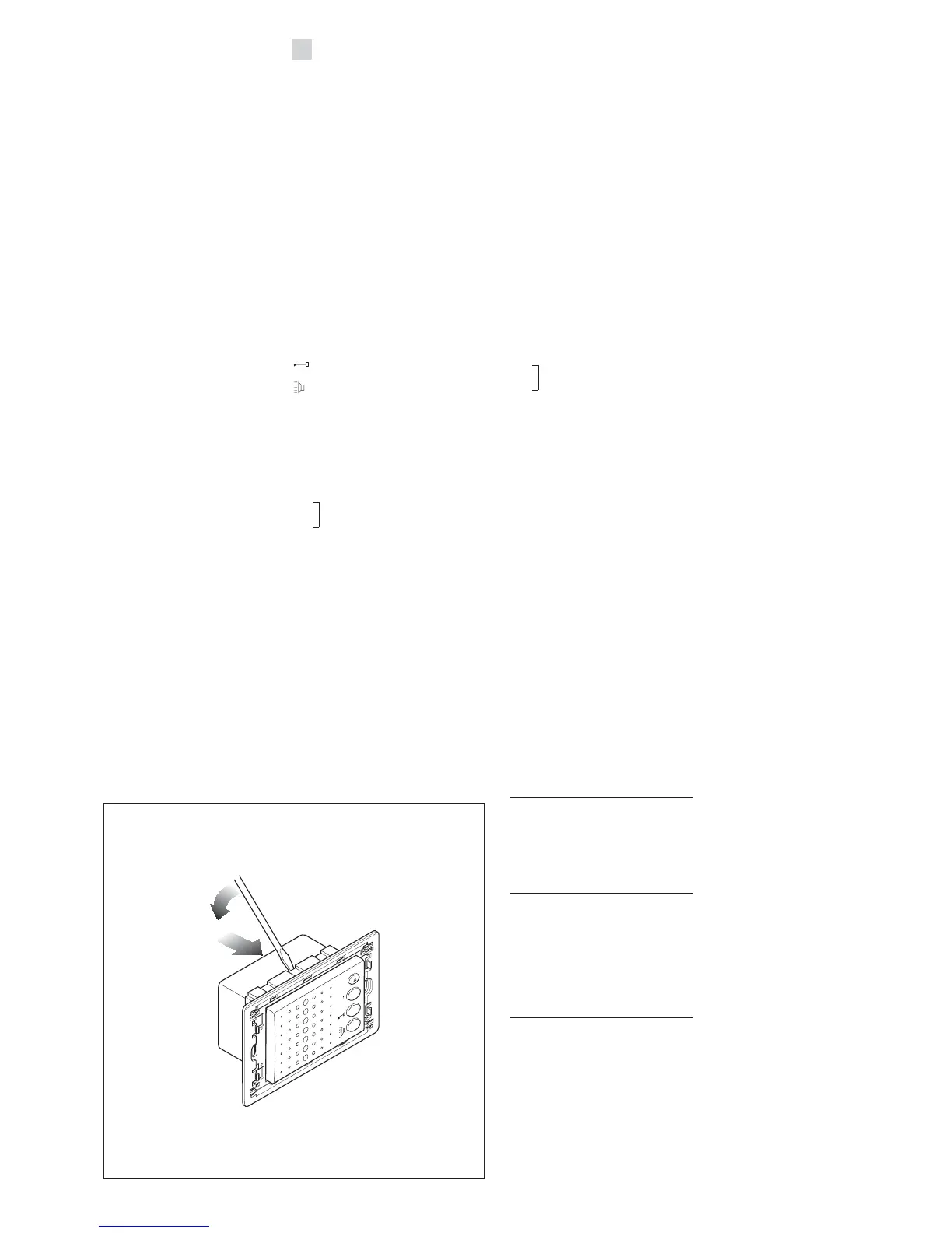
NOTE. If you need to remove the
module from the chassis, do so
with the aid of a screwdriver as illu-
strated in fig. 8 and push from the
back.