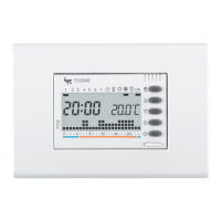
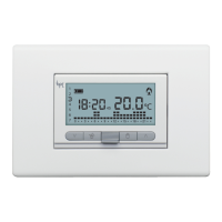
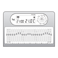
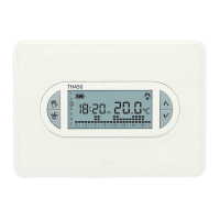
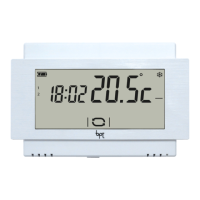
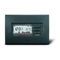
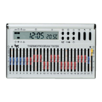
the use of different types of front
panel available on the market,
figure 9-10 and 11.
2 - ELECTRIC CONNECTIONS
The connections must be made
according to the type of equipment
being controlled by the thermostat;
refer, therefore, to the diagram in
figures 12A or 12B.
KEY
Mains power supply conductors
N = neutral
L = live
Relay conductors
C = common
NA = normally-open contact
NC = normally-closed contact
Loads
U1 = burner, water-circulating
pump, solenoid valve, etc.
U2 = motor-driven valve
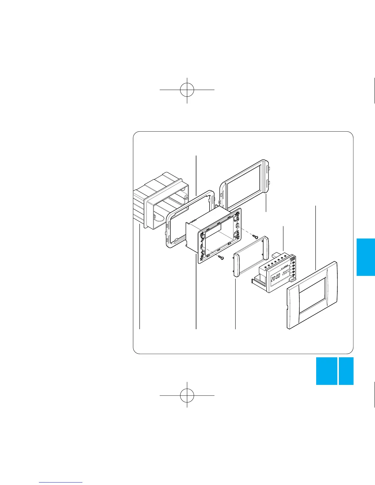
CHASSIS
3-MODULES
EMBEDDING
BOX
HOLE PLUG
ADAPTER
VIMAR
ADAPTER
AVE
ADAPTER
BODY
FRONT
PLATE:
VIMAR
(Serie Idea)
AVE
(System 45)
Fig. 10