S
Samuel MannAug 13, 2025
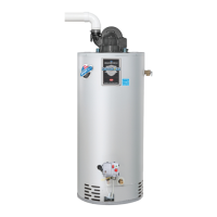
How to turn on my Bradford White RG1PV40S Water Heater if the control LED is not on?
- Jjason28Aug 13, 2025
If the control LED is not illuminated, first ensure that the control power switch is in the “ON” position. Also, check that the unit is receiving supply voltage and that it hasn't been interrupted. Turn the power on.