3
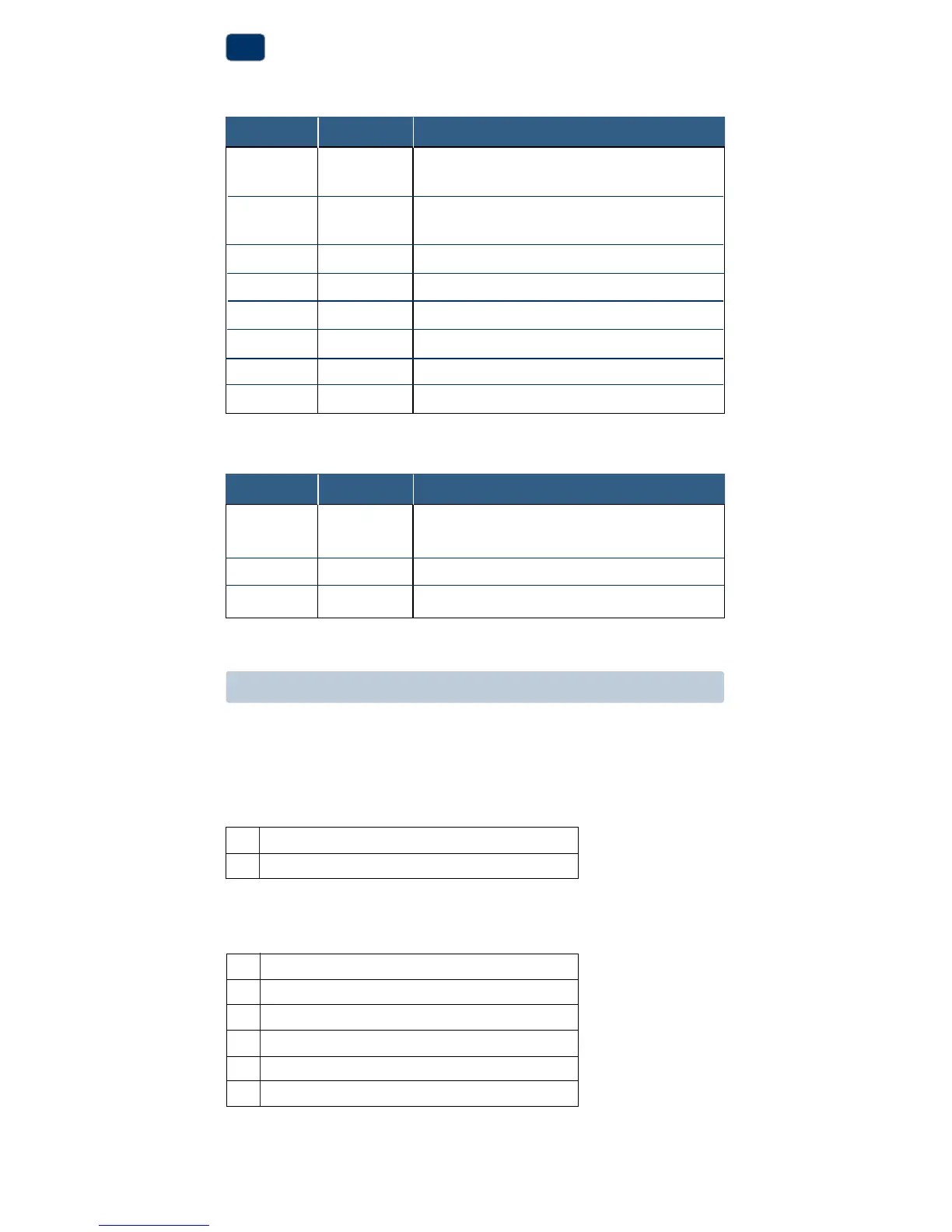
Terminal Function Description
Rc Input 24VoltACCoolingTransformer
(DualTransformerSystemsOnly)
Rh Input PowerConnection(24VoltACHeating
TransformerorMillivoltPowerSource)
O Output ReversingValve(CoolActive)
B Output ReversingValve(HeatActive)
Y1 Output CompressorRelay
G Output FanControl
W1 Output ConventionalHeatRelay
C Input 24VoltACTransformerCommon
Connect Your Wires
3
Wiring Terminations
Terminal Function Description
W1/E Output (W1)1stStageConventionalHeat
(E)EmergencyHeatRelay
Y2 Output
2ndStageConventionalCoolingCompressor
W2 Output 2ndStageHeat/AuxiliaryHeat
Additional Terminations (1220 only)
Heat Only or Millivolt
Set Installer Switch to CONV
Rh PowerConnection
W1 HeatRelay(appearsasW1/Eon1220)
1 HEAT / 1 COOL Single or Dual Transformer
Set Installer Switch to CONV
Rh
24VoltACPower(heatingtransformer)[note 2]
Rc
24VoltACPower(coolingtransformer)[note 2]
W1 HeatRelay(appearsasW1/Eon1220)
Y1 CompressorRelay
G FanRelay
C 24VoltACTransformerCommon[note 1, 3]
Typical Wiring Configurations
NOTE: The “Installer Switch” option will be configured in the next step.
Conventional Systems

 Loading...