EasyManua.ls Logo

Braeburn 1000NC User Manual

Braeburn 1000NC
11 pages
To Next Page IconTo Next Page
Page #1 background imageLoading...
Page #1 background image
This thermostat requires 24 Volt AC Power or two (2) properly installed
“AA Alkaline batteries for proper operation. When connecting 24 Volt
AC Power the batteries may be installed as a backup.
For use only as described in this manual. Any other use
will void warranty.
1000NC
Single Stage Heat / Cool
Conventional and Heat Pump
1
Specifications
2
About Your Thermostat
3
Installation
4
System Testing
5
Setting User Options
6
Operating Your Thermostat
7
Additional Operation Features
8
Thermostat Maintenance
®
Warning
Turn off power to the heating or cooling
equipment before installation.
Attention
For installation by experienced service
technicians only.
Follow applicable codes.
1200NC
Up to 2 Heat / 1 Cool
Conventional and Heat Pump
Read all instructions before proceeding.
This thermostat is compatible with:
• Singlestageheat/coolconventionalandheatpumpsystems
• Conventionalsystemsupto2heat/1cool(1200NConly)
• Singlecompressorheatpumpsystemswithanauxiliaryheatstage(1200NConly)
• 250–750millivoltheatonlysystems
Electrical and control specifications:
•ElectricalRating:24VoltAC
•1ampmaximumloadperterminal
•ACPower:18–30VoltsAC
•DCPower:3.0VoltDC(2“AA”AlkalineBatteriesIncluded)
•ControlRange:45°–90°F(7°–32°C)
•TemperatureAccuracy:+/-1°F(+/-.5°C)
Terminations
•1000NC–Rc,Rh,O,B,Y,W,G,C
•1200NC–R,O,B,Y1,E/W1,G,W2,C
1
Specifications
1000NCW-100-12
Non-Programmable
Thermostats
Model number is located on back of thermostat
Detailed
User Guide
Question and Answer IconNeed help?

Do you have a question about the Braeburn 1000NC and is the answer not in the manual?

Braeburn 1000NC Specifications

General IconGeneral
TypeNon-Programmable
DisplayLCD
ProgrammableNo
Number of Stages1 Heat / 1 Cool
Temperature Range45°F to 90°F
CompatibilitySingle Stage Heating and Cooling Systems

Summary

Specifications

About Your Thermostat

Room Temperature

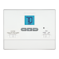
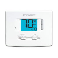
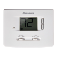
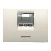
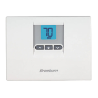
Displays the current room temperature.

Arrow Buttons

Used to increase or decrease settings.

System Switch

Selects Heat, Cool or Off.

Backlight Button

Illuminates the display backlight.

Low Battery Indicator

Indicates when the batteries need to be replaced.

System Status Indicator

Displays information about the status of the system.

Reset Button

Resets thermostat back to factory defaults.

Fan Switch

Selects the system fan mode.

Battery Compartment

Located in the back of the thermostat.

Installation

Install the Sub-Base

Mount the sub-base as shown below.

Provide Power

Connect 24VAC power or batteries.

Connect Your Wires

Wiring terminations and typical configurations.

Set Installer Switches

Configure system type, temperature scale, and heat type.

Attach Thermostat to Sub-Base

Connect thermostat body to the sub-base.

System Testing

System Testing Procedure

Test heating, cooling, and fan operations.

Setting User Options

Advanced User Options

Customize thermostat features via user options menu.

Table of User Options

Details on temperature differential settings.

Operating Your Thermostat

Setting the System Control Mode

Select COOL, OFF, HEAT, or EMER modes.

Setting the Fan Control Mode

Select AUTO or ON for fan operation.

Temperature Adjustment

Adjust the current set point temperature.

Status Indicators

Understand display icons for system status.

Additional Operation Features

Compressor Protection

Automatic delay to prevent short cycling.

Thermostat Maintenance

Resetting the Thermostat

Erase all user settings by pressing reset button.

Changing the Batteries

Replace AA batteries when low battery indicator appears.

Thermostat Cleaning

Clean outer body with a soft damp cloth.

Limited Warranty

Related product manuals